Page 16 of 2890

SERVICE
PROCEDURE
7
.
Combination
Switch
8)
Remove
steering
column
cowers
.
9)
Removing
two
retaining
screws,
remove
combination
switch
.
B
:
ADJUSTMENT
1
.
CENTERING
ROLL
CONNECTOR")
5-5b
[W7B1)
SERVICE
PROCEDURE
7
.
Combination
Switch
8)
Remove
steering
column
cowers
.
9)
Removing
two
retaining
screws,
remove
combination
switch
.
B
:
ADJUSTMENT
1
.
CENTERING
ROLL
CONNECTOR
Before
installing
steering
wheel,
make
sure
to
center
roil
connector
built
into
combination
switch
.
1)
Make
sure
that
front
wheels
are
positioned
straight
ahead
.
2)
Install
steering
gearbox,
steering
shaft
and
combina-
tion
switchproperly
.
Turn
roll
connector
pin
(J)
clockwise
until
it
stops
.
3)
Then,
back
off
roll
connector
pin
1~
approximately
2
.65
turns
until
"A"
marks
aligned
.
C
:
INSTALLATION
1)
Before
installing
combination
switch,
check
to
ensure
that
combination
switch
is
off
and
font
wheels
are
set
in
the
.straight
ahead
position
.
CAUTION
:
Failure
to
do
this
might
damage
roll
connoctok
.
2)
Install
column
cover
and
center
roll
connector
.
3)
Install
steering
wheel
in
neutral
position
.
Carefully
insert
roll
connector
pin
1(~
into
hole
on
steering
wheel
.
NOTE
:
If
steering
wheel
angle
requires
fine
adjustment,
adjust
tie-rod
.
<
Ref
.
to
4-3
[W3FOj
.*1
>
4)
Install
airbag
module
and
lower
cover
in
the
reverse
order
of
removal
.
6
Page 1029 of 2890
 Disconnect ground cable from battery.
2) Loosen front wheel nuts.
3) Lift-up vehicle, and remove front tires and wheels.
4) Remove both stabilizer and jack-u")
G4M0520
6. Front Crossmember
A: REMOVAL
1) Disconnect ground cable from battery.
2) Loosen front wheel nuts.
3) Lift-up vehicle, and remove front tires and wheels.
4) Remove both stabilizer and jack-up plate.
5) Disconnect tie-rod end from housing.
6) Remove front exhaust pipe.
G4M0521
7) Remove front transverse link from front crossmember
and body.
8) Remove nuts attaching engine mount cushion rubber to
crossmember.
9) Remove self-locking nuts connecting steering U/J and
pinion shaft.
10) Lift engine by approx. 10 mm (0.39 in) by using chain
block.
11) Support crossmember with a jack, remove nuts secur-
ing crossmember to body and lower crossmember gradu-
ally along with steering gearbox.
CAUTION:
When removing crossmember downward, be careful
that tie-rod end does not interfere with DOJ boot.
B: INSTALLATION
1) Installation is in the reverse order of removal proce-
dures.
CAUTION:
Always tighten rubber bushing when wheels are in full
contact with the ground and vehicle is at curb weight
condition.
Tightening torque:
Transverse link bushing to crossmember:
98±15 N⋅m (10.0±1.5 kg-m, 72±11 ft-lb)
Stabilizer to bushing:
25±4 N⋅m (2.5±0.4 kg-m, 18.1±2.9 ft-lb)
Tie-rod end to housing:
27.0±2.5 N⋅m (2.75±0.25 kg-m, 19.9±1.8 ft-lb)
Front cushion rubber to crossmember:
69±15 N⋅m (7.0±1.5 kg-m, 51±11 ft-lb)
Universal joint to pinion shaft:
24±3 N⋅m (2.4±0.3 kg-m, 17.4±2.2 ft-lb)
Crossmember to body:
98±15 N⋅m (10.0±1.5 kg-m, 72±11 ft-lb)
2) Purge air from power steering system.
NOTE:
Check wheel alignment and adjust if necessary.
28
4-1SERVICE PROCEDURE
6. Front Crossmember
Page 1108 of 2890
 5.3 (17.4) 5.6 (18.4)
Steering angle (Inside-Outside) 37.6°—32.6°34.4°—30.2°
S")
1. Steering System
A: SPECIFICATIONS
Except OUTBACK model OUTBACK model
Whole systemMinimum turning radius m (ft) 5.3 (17.4) 5.6 (18.4)
Steering angle (Inside-Outside) 37.6°—32.6°34.4°—30.2°
Steering wheel diameter mm (in) 385 (15.16)
Overall gear ratio (Turns, lock to lock) 16.5 (3.2) 19 (3.4)
GearboxType Rack and pinion, Integral
Backlash 0 (Automatically adjustable)
Valve (Power steering system) Rotary valve
Pump
(Power steering system)Type Vane pump
Oil tank Installed on pump
Output cm
3(cu in)/rev. 7.2 (0.439)
Relief pressure kPa (kg/cm
2, psi) 7,355 (75, 1,067)
Hydraulic fluid controlDropping in response to increased engine
revolutions
Hydraulic fluid�(US qt, Imp qt)1,000 rpm: 7 (7.4, 6.2)
3,000 rpm: 5 (5.3, 4.4)
Range of revolution rpm 500—7,500
Revolving direction Clockwise
Working fluid
(Power steering system)Name ATF DEXRON II, IIE or III
Capacity Oil tank�(US qt, Imp qt)
Total0.35 (0.4, 0.3)
0.7 (0.7, 0.6)
2
4-3SPECIFICATIONS AND SERVICE DATA
1. Steering System
Page 1109 of 2890
 17 (0.67)
Turning angleInner tire & wheel 37.6°34.4°
Outer tire & wheel 32.6°30.2°
Steering shaftClearance betwe")
B: SERVICE DATA
Except OUTBACK model OUTBACK model
Steering wheel Free play mm (in) 17 (0.67)
Turning angleInner tire & wheel 37.6°34.4°
Outer tire & wheel 32.6°30.2°
Steering shaftClearance between steering
wheel and column cover
mm (in)3.0 (0.118)
Steering gearbox
(Power steering system)Sliding resistance N (kg, lb) 240.3 (24.5, 54.0) or less
Rack shaft play in radial direc-
tion
mm (in)0.15 (0.0059) or less
Right-turn steering Horizontal movement: 0.3 (0.012) or less
Left-turn steering Vertical movement: 0.15 (0.0059) or less
Input shaft play mm (in)
In radial direction 0.18 (0.0071) or less
In axial direction 0.1 (0.004) or less
Turning resistance N (kg, lb)Within 30 mm (1.18 in) from rack center in straight ahead posi-
tion: Less than 11.18 (1.14, 2.51)
Maximum allowable value: 12.7 (1.3, 2.9)
Oil pump
(Power steering system)Pulley shaft mm (in)
Radial play 0.4 (0.016) or less
Axial play 0.9 (0.035) or less
Pulley
Ditch deflection mm (in)
Resistance to rotation
N (kg, lb)1.0 (0.039) or less
9.22 (0.94, 2.07) or less
Regular pressure
kPa (kg/cm
2, psi)981 (10, 142) or less
Relief pressure
kPa (kg/cm
2, psi)7,355 (75, 1,067)
Steering wheel effort
(Power steering system)At standstill with engine
idling on a concrete road
N (kg, lb)31.4 (3.2, 7.1) or less
At standstill with engine
stalled on a concrete road
N (kg, lb)147 (15, 33) or less
C: RECOMMENDED POWER STEERING
FLUID
Recommended power steering fluid Manufacturer
ATF DEXRON II, ATF DEXRON IIE or ATF
DEXRON IIIB.P.
CALTEX
CASTROL
MOBIL
SHELL
TEXACO
3
4-3SPECIFICATIONS AND SERVICE DATA
1. Steering System
Page 1120 of 2890
 Insert combination switch to upper column shaft, and
install lower column cover with tilt lever held in the lowered
position. Then route ignition key harness and combination
swi")
B4M0555
D: ASSEMBLY
1) Insert combination switch to upper column shaft, and
install lower column cover with tilt lever held in the lowered
position. Then route ignition key harness and combination
switch harness between column cover mounting bosses.
2) Fit upper column cover to lower column cover, and
tighten combination switch and column cover.
Tightening torque:
1.2±0.2 N⋅m (0.12±0.02 kg-m, 0.9±0.1 ft-lb)
CAUTION:
Don’t overtorque screw.
E: INSTALLATION
1) Insert end of steering shaft into toe board grommet.
2) Tighten steering shaft mounting bolts under instrument
panel.
Tightening torque:
25±5 N⋅m (2.5±0.5 kg-m, 18.1±3.6 ft-lb)
3) Connect ignition and combination switch connectors
under instrument panel.
4) Connect airbag system connector at harness spool.
NOTE:
Make sure to apply double lock.
5) Install universal joint.
(1) Align bolt hole on the long yoke side of universal
joint with the cutout at the serrated section of shaft end,
and insert universal joint.
(2) Align bolt hole on the short yoke side of universal
joint with the cutout at the serrated section of gearbox
assembly. Lower universal joint completely.
(3) Temporarily tighten bolt on the short yoke side.
Raise universal joint to make sure the bolt is properly
passing through the cutout at the serrated section.
(4) Tighten bolt on the long yoke side, then that on the
short yoke side.
Tightening torque:
24±3 N⋅m (2.4±0.3 kg-m, 17.4±2.2 ft-lb)
CAUTION:
�Make sure that universal joint bolts is tightened
through notch in shaft serration.
�Excessively large tightening torque of universal
joint bolts may lead to heavy steering wheel operation.
Standard clearance between gearbox to DOJ:
Over 15 mm (0.59 in)
13
4-3SERVICE PROCEDURE
2. Tilt Steering Column
Page 1122 of 2890
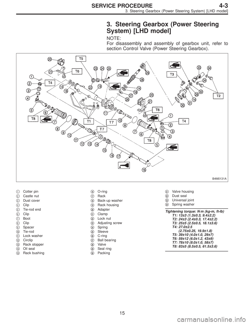
3. Steering Gearbox (Power Steering
System) [LHD model]
NOTE:
For disassembly and assembly of gearbox unit, refer to
section Control Valve (Power Steering Gearbox).
B4M0131A
�1Cotter pin
�
2Castle nut
�
3Dust cover
�
4Clip
�
5Tie-rod end
�
6Clip
�
7Boot
�
8Clip
�
9Spacer
�
10Tie-rod
�
11Lock washer
�
12Circlip
�
13Rack stopper
�
14Oil seal
�
15Rack bushing�
16O-ring
�
17Rack
�
18Back-up washer
�
19Rack housing
�
20Adapter
�
21Clamp
�
22Lock nut
�
23Adjusting screw
�
24Spring
�
25Sleeve
�
26C-ring
�
27Ball bearing
�
28Valve
�
29Seal ring
�
30Packing�
31Valve housing
�
32Dust seal
�
33Universal joint
�
34Spring washer
Tightening torque: N⋅m (kg-m, ft-lb)
T1: 13±3 (1.3±0.3, 9.4±2.2)
T2: 24±3 (2.4±0.3, 17.4±2.2)
T3: 25±5 (2.5±0.5, 18.1±3.6)
T4: 27.0±2.5
(2.75±0.25, 19.9±1.8)
T5: 39±10 (4.0±1.0, 29±7)
T6: 59±12 (6.0±1.2, 43±9)
T7: 78±10 (8.0±1.0, 58±7)
T8: 83±5 (8.5±0.5, 61.5±3.6)
15
4-3SERVICE PROCEDURE
3. Steering Gearbox (Power Steering System) [LHD model]
Page 1123 of 2890
A: REMOVAL
1) Disconnect battery minus terminal.
2) Loosen front wheel nut.
3) Lift vehicle and remove front wheels.
4) Remove front exhaust pipe assembly.
WARNING:
Be careful, exhaust pipe is hot.
G4M0097
5) Using a puller, remove tie-rod end from knuckle arm
after pulling off cotter pin and removing castle nut.
G4M0098
6) Remove jack-up plate and front stabilizer.
G4M0099
7) Remove one pipe joint at the center of gearbox, and
connect vinyl hose to pipe and joint. Discharge fluid by
turning steering wheel fully clockwise and counterclock-
wise. Discharge fluid similarly from the other pipe.
G4M0086
8) Remove lower side bolt of universal joint, then remove
upper side bolt and lift the joint upward.
NOTE:
Place a mark on the joint and mating serration so that they
can be re-installed at the original position.
16
4-3SERVICE PROCEDURE
3. Steering Gearbox (Power Steering System) [LHD model]
Page 1124 of 2890
G4M0101
9) Disconnect pipes C and D from pipe of gearbox.
CAUTION:
Be careful not to damage these pipes.
NOTE:
Disconnect upper pipe D first, and lower pipe C second.
G4M0102
10) Remove clamp bolts securing gearbox to
crossmember, and remove gearbox.
B4M0132A
B: DISASSEMBLY
1) Disconnect four pipes from gearbox.
2) Secure gearbox removed from vehicle in vice using ST.
ST 926200000 STAND
CAUTION:
Secure the gearbox in a vice using the ST as shown.
Do not attempt to secure it without this ST.
3) Remove tie-rod end and lock nut from gearbox.
G4M0104
4) Remove small clip from boot using pliers, and move
boot to tie-rod end side.
G4M0105
5) Remove boot together with large clips.
17
4-3SERVICE PROCEDURE
3. Steering Gearbox (Power Steering System) [LHD model]
 Disconnect battery minus terminal.
2) Loosen front wheel nut.
3) Lift vehicle and remove front wheels.
4) Remove front exhaust pipe assembly.
WARNING:
Be careful, exhaust pipe is hot.
G4")
 Disconnect pipes C and D from pipe of gearbox.
CAUTION:
Be careful not to damage these pipes.
NOTE:
Disconnect upper pipe D first, and lower pipe C second.
G4M0102
10) Remove clamp bolts se")