Page 1201 of 2890

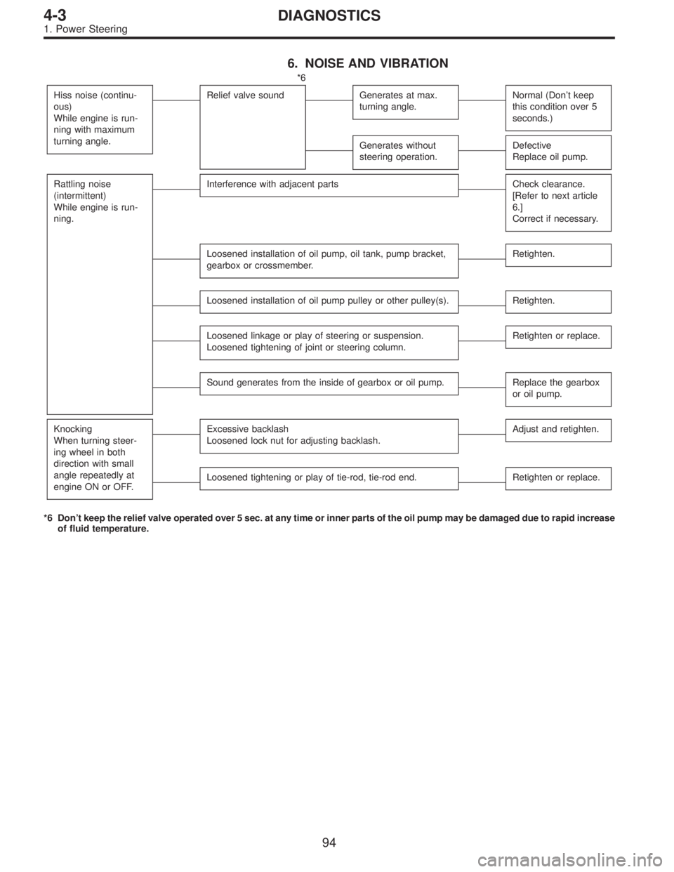
6. NOISE AND VIBRATION
*6
Hiss noise (continu-
ous)
While engine is run-
ning with maximum
turning angle.
Relief valve soundGenerates at max.
turning angle.Normal (Don’t keep
this condition over 5
seconds.)
Generates without
steering operation.Defective
Replace oil pump.
Rattling noise
(intermittent)
While engine is run-
ning.Interference with adjacent partsCheck clearance.
[Refer to next article
6.]
Correct if necessary.
Loosened installation of oil pump, oil tank, pump bracket,
gearbox or crossmember.Retighten.
Loosened installation of oil pump pulley or other pulley(s).Retighten.
Loosened linkage or play of steering or suspension.
Loosened tightening of joint or steering column.Retighten or replace.
Sound generates from the inside of gearbox or oil pump.Replace the gearbox
or oil pump.
Knocking
When turning steer-
ing wheel in both
direction with small
angle repeatedly at
engine ON or OFF.Excessive backlash
Loosened lock nut for adjusting backlash.Adjust and retighten.
Loosened tightening or play of tie-rod, tie-rod end.Retighten or replace.
*6 Don’t keep the relief valve operated over 5 sec. at any time or inner parts of the oil pump may be damaged due to rapid increase
of fluid temperature.
94
4-3DIAGNOSTICS
1. Power Steering
Page 1202 of 2890

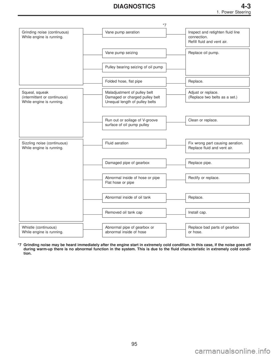
*7
Grinding noise (continuous)
While engine is running.
Vane pump aerationInspect and retighten fluid line
connection.
Refill fluid and vent air.
Vane pump seizingReplace oil pump.
Pulley bearing seizing of oil pump
Folded hose, flat pipeReplace.
Squeal, squeak
(intermittent or continuous)
While engine is running.Maladjustment of pulley belt
Damaged or charged pulley belt
Unequal length of pulley beltsAdjust or replace.
(Replace two belts as a set.)
Run out or soilage of V-groove
surface of oil pump pulleyClean or replace.
Sizzling noise (continuous)
While engine is running.Fluid aerationFix wrong part causing aeration.
Replace fluid and vent air.
Damaged pipe of gearboxReplace pipe.
Abnormal inside of hose or pipe
Flat hose or pipeRectify or replace.
Abnormal inside of oil tankReplace.
Removed oil tank capInstall cap.
Whistle (continuous)
While engine is running.Abnormal pipe of gearbox or
abnormal inside of hoseReplace bad parts of gearbox
or hose.
*7 Grinding noise may be heard immediately after the engine start in extremely cold condition. In this case, if the noise goes off
during warm-up there is no abnormal function in the system. This is due to the fluid characteristic in extremely cold condi-
tion.
95
4-3DIAGNOSTICS
1. Power Steering
Page 1203 of 2890

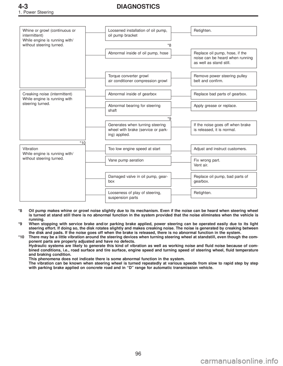
Whine or growl (continuous or
intermittent)
While engine is running with/
without steering turned.Loosened installation of oil pump,
oil pump bracketRetighten.
*8
Abnormal inside of oil pump, hoseReplace oil pump, hose, if the
noise can be heard when running
as well as stand still.
Torque converter growl
air conditioner compression growlRemove power steering pulley
belt and confirm.
Creaking noise (intermittent)
While engine is running with
steering turned.Abnormal inside of gearboxReplace bad parts of gearbox.
Abnormal bearing for steering
shaftApply grease or replace.
*9
Generates when turning steering
wheel with brake (service or park-
ing) applied.If the noise goes off when brake
is released, it is normal.
*10
Vibration
While engine is running with/
without steering turned.
Too low engine speed at startAdjust and instruct customers.
Vane pump aerationFix wrong part.
Vent air.
Damaged valve in oil pump, gear-
boxReplace oil pump, bad parts of
gearbox.
Looseness of play of steering,
suspension partsRetighten.
*8 Oil pump makes whine or growl noise slightly due to its mechanism. Even if the noise can be heard when steering wheel
is turned at stand still there is no abnormal function in the system provided that the noise eliminates when the vehicle is
running.
*9 When stopping with service brake and/or parking brake applied, power steering can be operated easily due to its light
steering effort. If doing so, the disk rotates slightly and makes creaking noise. The noise is generated by creaking between
the disk and pads. If the noise goes off when the brake is released, there is no abnormal function in the system.
*10 There may be a little vibration around the steering devices when turning steering wheel at standstill, even though the com-
ponent parts are properly adjusted and have no defects.
Hydraulic systems are likely to generate this kind of vibration as well as working noise and fluid noise because of com-
bined conditions, i.e., road surface and tire surface, engine speed and turning speed of steering wheel, fluid temperature
and braking condition.
This phenomena does not indicate there is some abnormal function in the system.
The vibration can be known when steering wheel is turned repeatedly at various speeds from slow to rapid step by step
with parking brake applied on concrete road and in“D”range for automatic transmission vehicle.
96
4-3DIAGNOSTICS
1. Power Steering
Page 1204 of 2890
7. CLEARANCE TABLE (LHD MODEL)
CAUTION:
This table lists various clearances that must be cor-
rectly adjusted to ensure normal vehicle driving with-
out interfering noise, or any other faults.
LocationMinimum
allowance
mm (in)LocationMinimum
allowance
mm (in)
�
1Crossmember—Pipe5 (0.20)�6Exhaust pipe—Pipe15 (0.59)
�
2DOJ—Shaft or joint14 (0.55)�7Exhaust pipe—Gearbox bolt15 (0.59)
�
3DOJ—Valve housing11 (0.43)�8Side frame—Hose A and B15 (0.59)
�
4Pipe—Pipe
2 (0.08)�
9Cruise control pump—Hose A and B15 (0.59)
Pipe—Crossmember�
10Pipe portion of hose A—Pipe portion of hose B1.5
(0.059)
�
5Stabilizer—Pipe5 (0.20)�11AT cooling hose—Joint20 (0.79)
B4M0565A
97
4-3DIAGNOSTICS
1. Power Steering
Page 1205 of 2890
8. CLEARANCE TABLE (RHD MODEL)
CAUTION:
This table lists various clearances that must be cor-
rectly adjusted to ensure normal vehicle driving with-
out interfering noise, or any other faults.
LocationMinimum
allowance
mm (in)LocationMinimum
allowance
mm (in)
�
1Crossmember—Pipe5 (0.20)�5Stabilizer—Pipe5 (0.20)
�
2DOJ—Shaft or joint14 (0.55)�6Exhaust pipe—Pipe15 (0.59)
�
3DOJ—Valve housing11 (0.43)�7Exhaust pipe—Gearbox boot15 (0.59)
�
4Pipe—Pipe
2 (0.08)�
8Side frame—Hose A and B15 (0.59)
Pipe—Crossmember�9Pipe portion of hose A—Pipe portion of hose B1.5
(0.059)
B4M0676A
98
4-3DIAGNOSTICS
1. Power Steering
Page 1592 of 2890
H5M0664
6) Disconnect airbag connector on back of airbag module.
Remove airbag module, and place it
with pad side facing upward.
G5M0332
7) Using steering puller, remove steering wheel.
CAUTION:
Do not allow connector to interfere when removing
steering wheel.
B5M0106
8) Remove steering column covers.
9) Removing two retaining screws, remove combination
switch.
B: ADJUSTMENT
1. CENTERING ROLL CONNECTOR
Before installing steering wheel, make sure to center roll
connector built into combination switch.
1) Make sure that front wheels are positioned straight
ahead.
2) Install steering gearbox, steering shaft and combination
switch properly. Turn roll connector pin�
1clockwise until
it stops.
H5M0663A
3) Then, back off roll connector pin�1approximately 2.65
turns until“�”marks aligned.
19
5-5SERVICE PROCEDURE
7. Combination Switch
Page 1613 of 2890
H5M0664
6) Disconnect airbag connector on back of airbag module.
Remove airbag module, and place it
with pad side facing upward.
G5M0332
7) Using steering puller, remove steering wheel.
CAUTION:
Do not allow connector to interfere when removing
steering wheel.
B5M0106
8) Remove steering column covers.
9) Removing two retaining screws, remove combination
switch.
B: ADJUSTMENT
1. CENTERING ROLL CONNECTOR
Before installing steering wheel, make sure to center roll
connector built into combination switch.
1) Make sure that front wheels are positioned straight
ahead.
2) Install steering gearbox, steering shaft and combination
switch properly. Turn roll connector pin�
1clockwiseuntil
it stops.
H5M0663A
3) Then, back off roll connector pin�1approximately 2.65
turns until“�”marks aligned.
17
5-5bSERVICE PROCEDURE
6. Combination Switch
Page 2880 of 2890

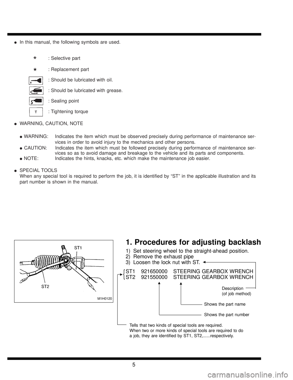
�In this manual, the following symbols are used.
*: Selective part
�: Replacement part
: Should be lubricated with oil.
: Should be lubricated with grease.
: Sealing point
: Tightening torque
�WARNING, CAUTION, NOTE
�WARNING: Indicates the item which must be observed precisely during performance of maintenance ser-
vices in order to avoid injury to the mechanics and other persons.
�CAUTION: Indicates the item which must be followed precisely during performance of maintenance ser-
vices so as to avoid damage and breakage to the vehicle and its parts and components.
�NOTE: Indicates the hints, knacks, etc. which make the maintenance job easier.
�SPECIAL TOOLS
When any special tool is required to perform the job, it is identified by“ST”in the applicable illustration and its
part number is shown in the manual.
M1H0120
1. Procedures for adjusting backlash
1) Set steering wheel to the straight-ahead position.
2) Remove the exhaust pipe
3) Loosen the lock nut with ST.
�
{ST1 921650000 STEERING GEARBOX WRENCH
ST2 921550000 STEERING GEARBOX WRENCH
Description
(of job method)
Shows the part name
Shows the part number
Tells that two kinds of special tools are required.
When two or more kinds of special tools are required to do
a job, they are identified by ST1, ST2,......respectively.
�
��
5