Page 1003 of 2890
1. Suspension
A: SPECIFICATIONS
1. STABILIZER
ModelBar dia. mm (in)
Front Rear
Sedan2200 cc 19 (0.75) 15 (0.59)
2500 cc 20 (0.79) 16 (0.63)
Wagon2200 cc 19 (0.75) 15 (0.59)
2500 cc 20 (0.79) 16 (0.63)
OUTBACK2200 cc 20 (0.79) 18 (0.71)
2500 cc 20 (0.79) 18 (0.71)
B: WHEEL ALIGNMENT
Sedan Wagon OUTBACK
FWD AWD FWD AWD AWD
FrontCamber
(tolerance: ±0°30′)�0°05′�0°05′�0°05′�0°05′0°20′
Caster
(tolerance: ±1°)3°05′3°05′3°05′3°05′2°50′
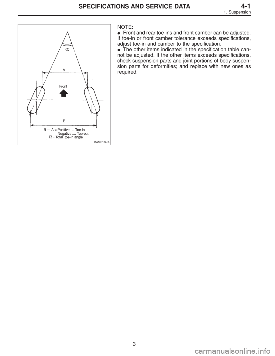
Toe-in mm (in) 0±3 (0±0.12) Total toe angle: 0°±20′
Kingpin angle (tolerance: ±1°) 14°15′14°15′14°15′14°15′13°30′
Wheel arch height
[tolerance:
+12
�24mm (+0.47
� 0.94in)] mm (in)385 (15.16) 385 (15.16) 385 (15.16) 385 (15.16) 420 (16.54)
RearCamber
(tolerance: ±0°45′)�0°55′�1° �0°45′�0°55′�0°35′
Toe-in mm (in) 0±3 (0±0.12) Total toe angle: 0°±20′
Wheel arch height
[tolerance:
+12
�24mm (+0.47
� 0.94in)] mm (in)369 (14.53) 369 (14.53) 379 (14.92) 379 (14.92) 419 (16.50)
Thrust angle 0°±20′
2
4-1SPECIFICATIONS AND SERVICE DATA
1. Suspension
Page 1004 of 2890
B4M0182A
NOTE:
�Front and rear toe-ins and front camber can be adjusted.
If toe-in or front camber tolerance exceeds specifications,
adjust toe-in and camber to the specification.
�The other items indicated in the specification table can-
not be adjusted. If the other items exceeds specifications,
check suspension parts and joint portions of body suspen-
sion parts for deformities; and replace with new ones as
required.
3
4-1SPECIFICATIONS AND SERVICE DATA
1. Suspension
Page 1005 of 2890

�6Rear bushing
�7Stop rubber (Front)
�8Ball joint
�9Transverse link
�10")
1. Conventional Suspension
1. FRONT SUSPENSION
B4M0765A
�1Front crossmember
�
2Bolt ASSY
�3Housing
�4Washer
�5Stop rubber (Rear)
�6Rear bushing
�7Stop rubber (Front)
�8Ball joint
�9Transverse link
�10Cotter pin
�11Front bushing
�12Stabilizer link
�13Clamp
�14Bushing (2200 cc model)
�15Stabilizer (2200 cc model)
�16Jack-up plate
�17Dust seal
�18Strut mount
�
19Spacer
�20Upper spring seat�
21Rubber seat
�22Dust cover
�23Helper
�24Coil spring
�25Damper strut
�26Adjusting bolt
�27Castle nut
�28Self-locking nut
�29Adapter front crossmember
(OUTBACK model)
�
30Clip (OUTBACK model)
�31Bushing
(2500 cc and OUTBACK model)
�
32Clamp
(2500 cc and OUTBACK model)
Tightening torque: N⋅m (kg-m, ft-lb)
T1: 18±5 (1.8±0.5, 13.0±3.6)
T2: 20±6 (2.0±0.6, 14.5±4.3)
T3: 25±4 (2.5±0.4, 18.1±2.9)
T4: 29±5 (3.0±0.5, 21.7±3.6)
T5: 39 (4, 29)
T6: 44±6 (4.5±0.6, 32.5±4.3)
T7: 49±10 (5.0±1.0, 36±7)
T8: 54±5 (5.5±0.5, 39.8±3.6)
T9: 98±15 (10.0±1.5, 72±11)
T10:152±20 (15.5±2.0, 112±14)
T11:186±10 (19.0±1.0, 137±7)
T12:245±49 (25.0±5.0, 181±36)
4
4-1COMPONENT PARTS
1. Conventional Suspension
Page 1006 of 2890

B4M0766A
�1Stabilizer
�
2Stabilizer bracket
�
3Stabilizer bushing
�
4Clamp
�
5Floating bushing
�
6Stopper
�
7Stabilizer link
�
8Rear lateral link
�
9Bushing (C)
�
10Bush")
2. REAR SUSPENSION (AWD MODEL)
B4M0766A
�1Stabilizer
�
2Stabilizer bracket
�
3Stabilizer bushing
�
4Clamp
�
5Floating bushing
�
6Stopper
�
7Stabilizer link
�
8Rear lateral link
�
9Bushing (C)
�
10Bushing (A)
�
11Front lateral link
�
12Bushing (B)
�
13Trailing link rear bushing
�
14Trailing link
�
15Trailing link front bushing�
16Trailing link bracket
�
17Cap (Protection)
�
18Washer
�
19Rear crossmember
�
20Strut mount cap
�
21Strut mount
�
22Rubber seat upper
�
23Dust cover
�
24Coil spring
�
25Helper
�
26Rubber seat lower
�
27Damper strut
�
28Self-locking nut
�
29Crossmember reinforcement
lower (Sedan model)
�
30Adapter rear crossmember
(OUTBACK model)
Tightening torque: N⋅m (kg-m, ft-lb)
T1: 20±6 (2.0±0.6, 14.5±4.3)
T2: 25±7 (2.5±0.7, 18.1±5.1)
T3: 44±6 (4.5±0.6, 32.5±4.3)
T4: 59±10 (6.0±1.0, 43±7)
T5: 98±15 (10.0±1.5, 72±11)
T6: 98±20 (10.0±2.0, 72±14)
T7: 113±15 (11.5±1.5, 83±11)
T8: 127±20 (13.0±2.0, 94±14)
T9: 137±20 (14.0±2.0, 101±14)
T10:196
+39
�10(20.0+4.0
�1.0, 145+29
�7)
5
4-1COMPONENT PARTS
1. Conventional Suspension
Page 1007 of 2890
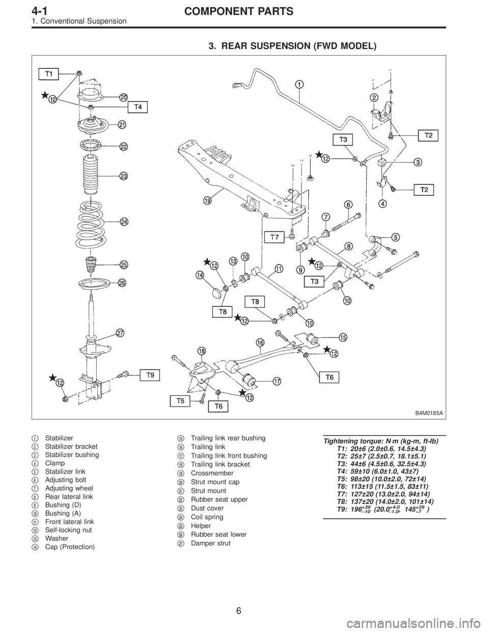
3. REAR SUSPENSION (FWD MODEL)
B4M0185A
�1Stabilizer
�
2Stabilizer bracket
�
3Stabilizer bushing
�
4Clamp
�
5Stabilizer link
�
6Adjusting bolt
�
7Adjusting wheel
�
8Rear lateral link
�
9Bushing (D)
�
10Bushing (A)
�
11Front lateral link
�
12Self-locking nut
�
13Washer
�
14Cap (Protection)�
15Trailing link rear bushing
�
16Trailing link
�
17Trailing link front bushing
�
18Trailing link bracket
�
19Crossmember
�
20Strut mount cap
�
21Strut mount
�
22Rubber seat upper
�
23Dust cover
�
24Coil spring
�
25Helper
�
26Rubber seat lower
�
27Damper strut
Tightening torque: N⋅m (kg-m, ft-lb)
T1: 20±6 (2.0±0.6, 14.5±4.3)
T2: 25±7 (2.5±0.7, 18.1±5.1)
T3: 44±6 (4.5±0.6, 32.5±4.3)
T4: 59±10 (6.0±1.0, 43±7)
T5: 98±20 (10.0±2.0, 72±14)
T6: 113±15 (11.5±1.5, 83±11)
T7: 127±20 (13.0±2.0, 94±14)
T8: 137±20 (14.0±2.0, 101±14)
T9: 196
+39
�10(20.0+4.0
�1.0, 145+29
�7)
6
4-1COMPONENT PARTS
1. Conventional Suspension
Page 1015 of 2890
 Position vehicle on a level surface.
2) Move vehicle 3 to 4 meters directly forward.
3) Determine locus of both front and rear axles.
4) Measure distance“L”b")
G4M0488
6. THRUST ANGLE
�Inspection
1) Position vehicle on a level surface.
2) Move vehicle 3 to 4 meters directly forward.
3) Determine locus of both front and rear axles.
4) Measure distance“L”between center line of loci of the
axles.
Thrust angle is less than 20’when“L”is equal to or less
than 15 mm (0.59 in).
�Adjustment
Make thrust angle adjustments by turning toe-in adjusting
bolts of rear suspension equally in the same direction.
NOTE:
On FWD models, turn adjusting wheels one by one, by the
some amount in the opposite direction of the adjusting
bolts.
When one rear wheel is adjusted in a toe-in direction,
adjust the other rear wheel equally in toe-out direction, in
order to make thrust angle adjustment.
When left and right adjusting bolts are turned incremen-
tally by one graduation in the same direction, the thrust
angle of the AWD model will change approximately 10’[“L”
is almost equal to 7.5 mm (0.295 in)] and the thrust angle
of the FWD model will change approximately 12’[“L”is
almost equal to 9 mm (0.35 in)].
Thrust angle:
0°±20′
B4M0193A
NOTE:
Thrust angle refers to a mean value of left and right rear
wheel toe angles in relation to vehicle body center line.
Vehicle is driven straight in the thrust angle direction while
swinging in the oblique direction depending on the degree
of the mean thrust angle.
B4M0194A
Thrust angle: r
r=α�β2
α: Right rear wheel toe angle
β: Left rear wheel toe angle
NOTE:
Here, use only positive toe-in values from each wheel to
substitute forαandβin the equation.
14
4-1SERVICE PROCEDURE
1. On-car Services
Page 1291 of 2890

18. Brake Hose and Pipe
SUPPLEMENTAL RESTRAINT SYSTEM“AIRBAG”
Airbag system wiring harness is routed near the center
brake pipe.
CAUTION:
�All Airbag system wiring harness and connectors
are colored yellow. Do not use electrical test equip-
ment on these circuit.
�Be careful not to damage Airbag system wiring har-
ness when servicing the center brake pipe.
A: REMOVAL AND INSTALLATION
CAUTION:
�When removing and installing the brake pipe, make
sure that it is not bent.
�After installing the brake pipe and hose, bleed the
air.
�After installing the brake hose, make sure that it
does not touch the tire or suspension assembly, etc.
1. MODELS WITHOUT ABS
G4M0472
�1Union bolt
�
2Front brake hose RH
�
3Proportioning valve
�
4Front brake pipe
�
5Front adapter pipe (UPPER)
�
6Front adapter pipe (LOWER)
�
7Front brake hose LH�
8Center brake pipe ASSY
�
9Connector bracket
�
10Two-way connector
�
11Rear brake pipe RH
�
12Rear brake hose drum
�
13Rear brake pipe ASSY
�
14Rear brake pipe LH
Tightening torque: N⋅m (kg-m, ft-lb)
T1: 13±3 (1.3±0.3, 9.4±2.2)
T2: 15
+3
�2(1.5+0.3
�0.2, 10.8+2.2
�1.4)
T3: 18±3 (1.8±0.3, 13.0±2.2)
T4: 18±5 (1.8±0.5, 13.0±3.6)
82
4-4SERVICE PROCEDURE
18. Brake Hose and Pipe
Page 1434 of 2890
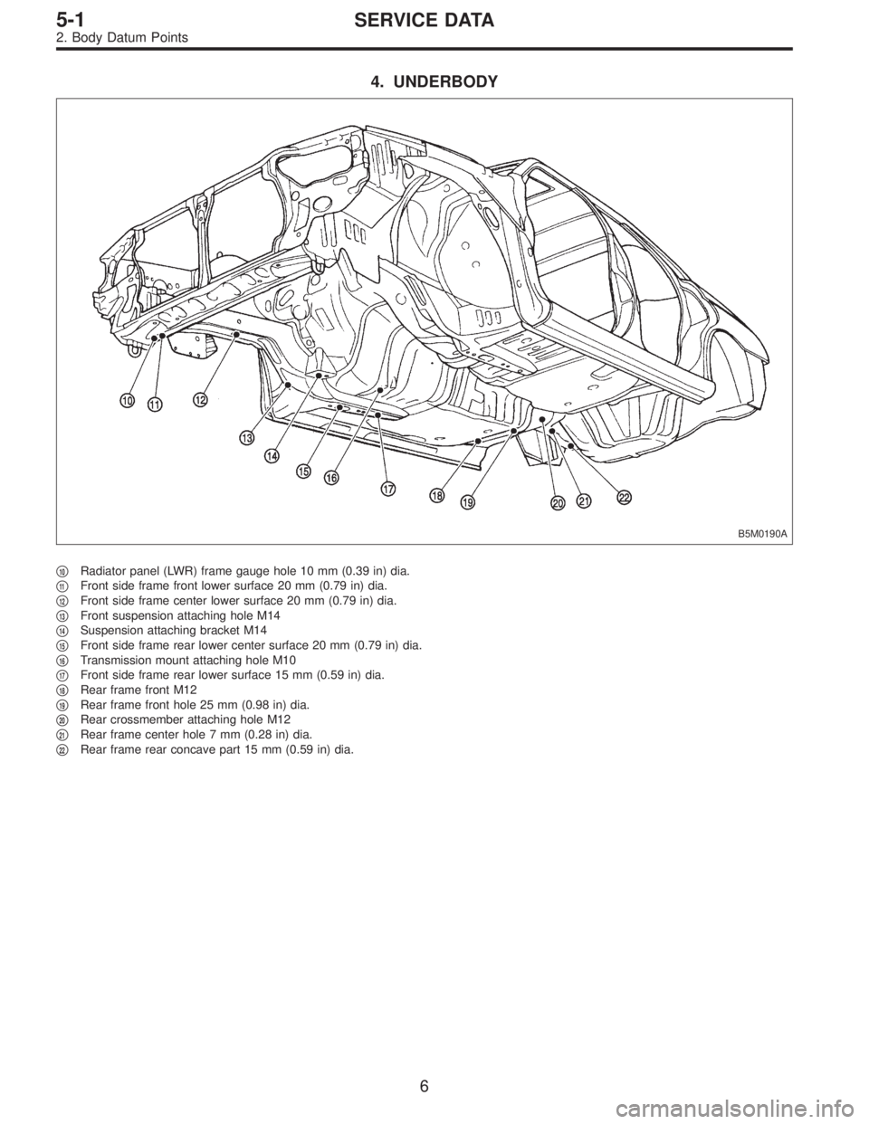
4. UNDERBODY
B5M0190A
�10Radiator panel (LWR) frame gauge hole 10 mm (0.39 in) dia.
�
11Front side frame front lower surface 20 mm (0.79 in) dia.
�
12Front side frame center lower surface 20 mm (0.79 in) dia.
�
13Front suspension attaching hole M14
�
14Suspension attaching bracket M14
�
15Front side frame rear lower center surface 20 mm (0.79 in) dia.
�
16Transmission mount attaching hole M10
�
17Front side frame rear lower surface 15 mm (0.59 in) dia.
�
18Rear frame front M12
�
19Rear frame front hole 25 mm (0.98 in) dia.
�
20Rear crossmember attaching hole M12
�
21Rear frame center hole 7 mm (0.28 in) dia.
�
22Rear frame rear concave part 15 mm (0.59 in) dia.
6
5-1SERVICE DATA
2. Body Datum Points

Front Rear
Sedan2200 cc 19 (0.75) 15 (0.59)
2500 cc 20 (0.79) 16 (0.63)
Wagon2200 cc 19 (0.75) 15 (0.59)
2500 cc 20 (0.79) 16 (0.63)")