Page 18 of 2890
![SUBARU LEGACY 1996 Service Repair Manual
ON-BOARD
DIAGNOSTICS
II
SYSTEM
[Tiq2]
2-
1
.
General
1~
Engine
control
module
(ECM)
~
Radiator
fan
~2
Ignition
coil~s
Radiator
fan
relay
~3
Ignitqr
~s
Pressure
sources
switching
solenoid
valve
~](/manual-img/17/57433/w960_57433-17.png "SUBARU LEGACY 1996 Service Repair Manual
ON-BOARD
DIAGNOSTICS
II
SYSTEM
[Tiq2]
2-
1
.
General
1~
Engine
control
module
(ECM)
~
Radiator
fan
~2
Ignition
coil~s
Radiator
fan
relay
~3
Ignitqr
~s
Pressure
sources
switching
solenoid
valve
~")
ON-BOARD
DIAGNOSTICS
II
SYSTEM
[Tiq2]
2-
1
.
General
1~
Engine
control
module
(ECM)
~
Radiator
fan
~2
Ignition
coil~s
Radiator
fan
relay
~3
Ignitqr
~s
Pressure
sources
switching
solenoid
valve
~4
Crankshaft
position
sensor
~
Knock
sensor
~5
Camshaft
position
sensor
~
Back-pressure
transducer
Throttle
position
sensor
~s
Front
oxygen
sensor
~7
duel
injectors
~o
Rear
oxygen
sensor
(Except
California
model)
~8
Pressure
regulator
~
Pressure
sensor
Engine
coolant
temperature
sensor
~z
A/C
compressor
~o
Mass
air
flow
sensor
~
Inhibitor
switch
Idle
air
control
solenoid
valve
~
CHECK
ENGINE
malfunction
indicator
lamp
(MIL)
~z
Purge
control
solenoid
valve
~
Tachometer
0
Fuel
pump
~s
A/C
relay
0
PCV
valve
~
A/C
control
module
~s
Air
cleaner
~eIgnition
switch
Canister
~
Transmission
control
module
(TCM)
~
Main
relay
~o
Vehicle
speed
sensor
2
~a
Fuel
pump
relay
~
Data
link
connector
(For
Subaru
select
monitor)
~s
Fuel
filter
@
Data
link
connector
(For
Subaru
select
monitor
and
~o
Front
catalytic
converter
OBD-II
general
scan
tool)
Rear
catalytic
converter
@
Two
way
valve
~2
MGR
valve
~a
Rear
oxygen
sensor
(California
model
only)
EGR
control
solenoid
valve
~
Filter
3
Page 80 of 2890

ON-BOARD
DIAGNOSTICS
II
SYSTEM
[Tyooyl
2-7
10
.
General
Diagnostics
Table
10
.
General
Diagnostics
Table
1
.
FOR
ENGINE
1
23
4
5678
9
10
11
1213
N
ONCdN
C
O
O
a
x
m
Problem
parts
`o
m
v
mj
4'S
O
1>j
T
N
dm
G
~
ON
41
m
~
!d
V
P]
7
0
E
m
~n
N
~o
C
o
O
d
~
~
U
O
c
m~
C
.
.
.
V1
ON
aVa
U
3
C~
0
"
y
dO1OyOQ
~
"O
CN
d7
O
"
0va
l0
0CdyGo
>
"
Vd
da
E
U
"
O
l0
ymC
~
O
NC
N
V
V
4)
N
~
'C
C
.2
7
a
3NmC
oi
mm
o
W
m
.
mU
o~
Symptom
2WFU~Ya
LL
.0
ti
QW
1
Engine
stalls
during
idling
.
O4OOOOO
2
Rough
idling
O
4O
Cl
OO
3
Engine
does
notreturnto
idle
.
O
OO
4Poor
acceleration
O4OOOOO
Engine
stalls
or
engine
sags
or
hesi-
O
D
OOOOOO
fates
at
acceleration
.
6
Surge
O4OOOO
T
Spark
knock
OOOO
8
After
burning
in
exhaust
system
O
Lr
I
O
I
'1
:
The
mark,
D,
indicates
the
symptom
occurring
only
in
cold
temperatures
.
'2
:
For
itemswiththe
mark,
D,ensure
the
secure
installationof
crankshaft
position
sensor
and
camshaft
position
sensor
.
Replacement
is
not
necessary
.
'3
:
Check
fuel
injector,
fuel
pressure
regulator
and
fuel
filter
.
'4
:
Check
ignitor,
ignition
coil
and
spark
plug
.
NOTE
:
Malfunction
of
partsother
than
the
above
is
also
possible
.
Refer
to
1
.
Engine
Trouble
in
General
[K100]
in
Repair
Section
2-3
of
the
Service
Manual
69
Page 297 of 2890
G6M0095
11. Vent Control Solenoid Valve (2200
cc AWD Model)
A: REMOVAL
1) Disconnect battery ground cable.
B2M0964
2) Lift-up the vehicle.
3) Remove canister.
4) Disconnect two hoses from air filter.
5) Disconnect connector from vent control solenoid valve.
H2M1469
6) Remove one bolt fixing bracket on the body.
B2M0965A
7) Remove two vacuum hoses from vent control solenoid
valve.
B2M0966
8) Remove one bolt fixing vent control solenoid valve on
bracket.
9) Remove vent control solenoid valve.
13
2-1SERVICE PROCEDURE
11. Vent Control Solenoid Valve (2200 cc AWD Model)
Page 298 of 2890
B2M0966
B: INSTALLATION
1) Install the bolt fixing vent control solenoid valve on
bracket.
B2M0965A
2) Install two vacuum hoses to vent control solenoid valve.
H2M1469
3) Install the bolt fixing bracket on the body.
Tightening torque:
25±7 N⋅m (2.5±0.7 kg-m, 18.1±5.1 ft-lb)
B2M0964
4) Connect connector to vent control solenoid valve.
5) Connect two hoses to air filter.
6) Install canister.
7) Let down the vehicle.
G6M0095
8) Connect battery ground cable.
14
2-1SERVICE PROCEDURE
11. Vent Control Solenoid Valve (2200 cc AWD Model)
Page 300 of 2890
 Remove two screws fixing bracket on fuel pump assem-
bly.
H2M1461A
8) Remove one screw fixing fuel level sensor on bracket.
9) Remove fuel level sensor from fuel pump assembly.
B2M0955A
B:")
H2M1460
7) Remove two screws fixing bracket on fuel pump assem-
bly.
H2M1461A
8) Remove one screw fixing fuel level sensor on bracket.
9) Remove fuel level sensor from fuel pump assembly.
B2M0955A
B: INSTALLATION
CAUTION:
Leave fuel filler cap open when tightening nuts, to pre-
vent fuel from flowing out through fuel delivery and
return pipes. Close fuel filler cap after tightening nuts.
Installation is in the reverse order of removal. Do the fol-
lowing:
(1) Always use new gaskets.
(2) Ensure sealing portion is free from fuel or foreign
particles before installation.
(3) Tighten nuts in numerical sequence shown in Fig-
ure to specified torque.
Tightening torque:
4.4±1.5 N⋅m (0.45±0.15 kg-m, 3.3±1.1 ft-lb)
B2M0968
13. Air Filter (2200 cc AWD Model)
A: REMOVAL AND INSTALLATION
1) Remove canister.
2) Remove two hoses from air filter.
3) Remove flange nut from bracket.
4) Installation is in the reverse order of removal.
16
2-1SERVICE PROCEDURE
12. Fuel Level Sensor (2200 cc AWD Model) - 13. Air Filter (2200 cc AWD Model)
Page 301 of 2890
 Remove two screws fixing bracket on fuel pump assem-
bly.
H2M1461A
8) Remove one screw fixing fuel level sensor on bracket.
9) Remove fuel level sensor from fuel pump assembly.
B2M0955A
B:")
H2M1460
7) Remove two screws fixing bracket on fuel pump assem-
bly.
H2M1461A
8) Remove one screw fixing fuel level sensor on bracket.
9) Remove fuel level sensor from fuel pump assembly.
B2M0955A
B: INSTALLATION
CAUTION:
Leave fuel filler cap open when tightening nuts, to pre-
vent fuel from flowing out through fuel delivery and
return pipes. Close fuel filler cap after tightening nuts.
Installation is in the reverse order of removal. Do the fol-
lowing:
(1) Always use new gaskets.
(2) Ensure sealing portion is free from fuel or foreign
particles before installation.
(3) Tighten nuts in numerical sequence shown in Fig-
ure to specified torque.
Tightening torque:
4.4±1.5 N⋅m (0.45±0.15 kg-m, 3.3±1.1 ft-lb)
B2M0968
13. Air Filter (2200 cc AWD Model)
A: REMOVAL AND INSTALLATION
1) Remove canister.
2) Remove two hoses from air filter.
3) Remove flange nut from bracket.
4) Installation is in the reverse order of removal.
16
2-1SERVICE PROCEDURE
12. Fuel Level Sensor (2200 cc AWD Model) - 13. Air Filter (2200 cc AWD Model)
Page 484 of 2890
 O")
1. Engine Lubrication System
Before troubleshooting, make sure that the engine oil level
is correct and no oil leakage exists.
Trouble Possible cause Corrective action
1. Warning light remains
on.1) Oil pressure switch
failureCracked diaphragm or oil leakage within switch Replace.
Broken spring or seized contacts Replace.
2) Low oil pressureClogged oil filter Replace.
Malfunction of oil by-pass valve of oil filter Clean or replace.
Malfunction of oil relief valve of oil pump Clean or replace.
Clogged oil passage Clean.
Excessive tip clearance and side clearance of oil
pump rotor and gearReplace.
Clogged oil strainer or broken pipe Clean or replace.
3) No oil pressureInsufficient engine oil Replenish.
Broken pipe of oil strainer Replace.
Stuck oil pump rotor Replace.
2. Warning light does not
go on.1) Burn-out bulb Replace.
2) Poor contact of switch contact points Replace.
3) Disconnection of wiring Repair.
3. Warning light flickers
momentarily.1) Poor contact at terminals Repair.
2) Defective wiring harness Repair.
3) Low oil pressureCheck for the same pos-
sible causes as listed in
1.—2)
17
2-4DIAGNOSTICS
1. Engine Lubrication System
Page 556 of 2890
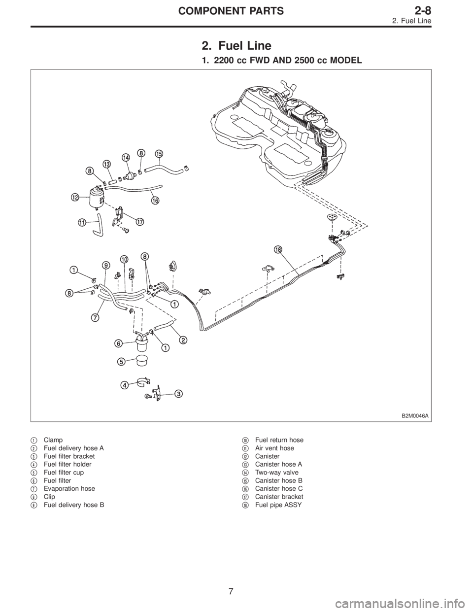
2. Fuel Line
1. 2200 cc FWD AND 2500 cc MODEL
B2M0046A
�1Clamp
�
2Fuel delivery hose A
�
3Fuel filter bracket
�
4Fuel filter holder
�
5Fuel filter cup
�
6Fuel filter
�
7Evaporation hose
�
8Clip
�
9Fuel delivery hose B�
10Fuel return hose
�
11Air vent hose
�
12Canister
�
13Canister hose A
�
14Two-way valve
�
15Canister hose B
�
16Canister hose C
�
17Canister bracket
�
18Fuel pipe ASSY
7
2-8COMPONENT PARTS
2. Fuel Line
![SUBARU LEGACY 1996 Service Repair Manual G6M0095
11. Vent Control Solenoid Valve (2200
cc AWD Model)
A: REMOVAL
1) Disconnect battery ground cable.
B2M0964
2) Lift-up the vehicle.
3) Remove canister. <Ref. to 2-1 [W3A2].>
4) Disconnect two h](/manual-img/17/57433/w960_57433-296.png "SUBARU LEGACY 1996 Service Repair Manual G6M0095
11. Vent Control Solenoid Valve (2200
cc AWD Model)
A: REMOVAL
1) Disconnect battery ground cable.
B2M0964
2) Lift-up the vehicle.
3) Remove canister. <Ref. to 2-1 [W3A2].>
4) Disconnect two h")
 Install the bolt fixing vent control solenoid valve on
bracket.
B2M0965A
2) Install two vacuum hoses to vent control solenoid valve.
H2M1469
3) Install the bolt fixing brack")