Page 562 of 2890
G2M0345
3. Fuel Tank
A: REMOVAL
1) Release fuel pressure.
2) Drain fuel from fuel tank.
G2M0382
3) Remove rear exhaust pipe.
(1) Lift-up the vehicle.
(2) Separate rear exhaust pipe from center exhaust
pipe.
(3) Separate rear exhaust pipe from muffler.
(4) Remove bracket from rubber cushion, and remove
exhaust pipe.
NOTE:
To facilitate the removal of parts, apply a coat of SUBARU
CRC5-56 (Part No. 004301003)
G2M0384
4) Remove muffler assembly.
NOTE:
To facilitate the removal of parts, apply a coat of SUBARU
CRC5-56 (Part No. 004301003)
G3M0059
5) Remove rear differential assembly. (AWD model)
(1) Remove rear axle shafts from rear differential
assembly.
(2) Remove rear differential front cover.
(3) Remove propeller shaft.
(4) Remove lower differential bracket.
(5) Set transmission jack under rear differential.
(6) Remove bolts which install rear differential onto
rear crossmember.
13
2-8SERVICE PROCEDURE
3. Fuel Tank
Page 671 of 2890
G2M0345
3. Fuel Tank
A: REMOVAL
1) Release fuel pressure.
2) Drain fuel from fuel tank.
G2M0382
3) Remove rear exhaust pipe.
(1) Lift-up the vehicle.
(2) Separate rear exhaust pipe from center exhaust
pipe.
(3) Separate rear exhaust pipe from muffler.
(4) Remove bracket from rubber cushion, and remove
exhaust pipe.
NOTE:
To facilitate the removal of parts, apply a coat of SUBARU
CRC5-56 (Part No. 004301003)
G2M0384
4) Remove muffler assembly.
NOTE:
To facilitate the removal of parts, apply a coat of SUBARU
CRC5-56 (Part No. 004301003)
G3M0059
5) Remove rear differential assembly. (AWD model)
(1) Remove rear axle shafts from rear differential
assembly.
(2) Remove rear differential front cover.
(3) Remove propeller shaft.
(4) Remove lower differential bracket.
(5) Set transmission jack under rear differential.
(6) Remove bolts which install rear differential onto
rear crossmember.
13
2-8SERVICE PROCEDURE
3. Fuel Tank
Page 761 of 2890

Snap ring (Inner-110) to center differential case clearance
0—0.15 mm (0—0.0059 in)
Snap ring (Inner-110)
Part No. Thickness mm (in)
805100061 2.10 (0.0827)
8051")
9. CENTER DIFFERENTIAL (AWD Model)
Snap ring (Inner-110) to center differential case clearance
0—0.15 mm (0—0.0059 in)
Snap ring (Inner-110)
Part No. Thickness mm (in)
805100061 2.10 (0.0827)
805100062 2.21 (0.0870)
805100063 2.32 (0.0913)
Backlash adjustment axial movement
0.62—0.86 mm (0.0244—0.0339 in)
Adjusting washer (45 x 62 x t)
Part No. Thickness mm (in)
803045041 1.60 (0.0630)
803045042 1.80 (0.0709)
803045043 2.00 (0.0787)
803045044 2.20 (0.0866)
803045045 2.40 (0.0945)
10. FRONT DIFFERENTIAL
Bevel gear to pinion backlash
0.13—0.18 mm (0.0051—0.0071 in)
Washer (38.1 x 50 x t)
Part No.Thickness
mm (in)Part No.Thickness
mm (in)
8030380210.925—
0.950
(0.0364—
0.0374)8030380231.025—
1.050
(0.0404—
0.0413)
8030380220.975—
1.000
(0.0384—
0.0394)
Pinion shaft to axle drive shaft clearance
0—0.2 mm (0—0.008 in)
Snap ring (Outer-28)
Part No.Thickness
mm (in)Part No.Thickness
mm (in)
805028011 1.05 (0.0413) 805028012 1.20 (0.0472)
5
3-1SPECIFICATIONS AND SERVICE DATA
1. Manual Transmission and Differential
Page 770 of 2890
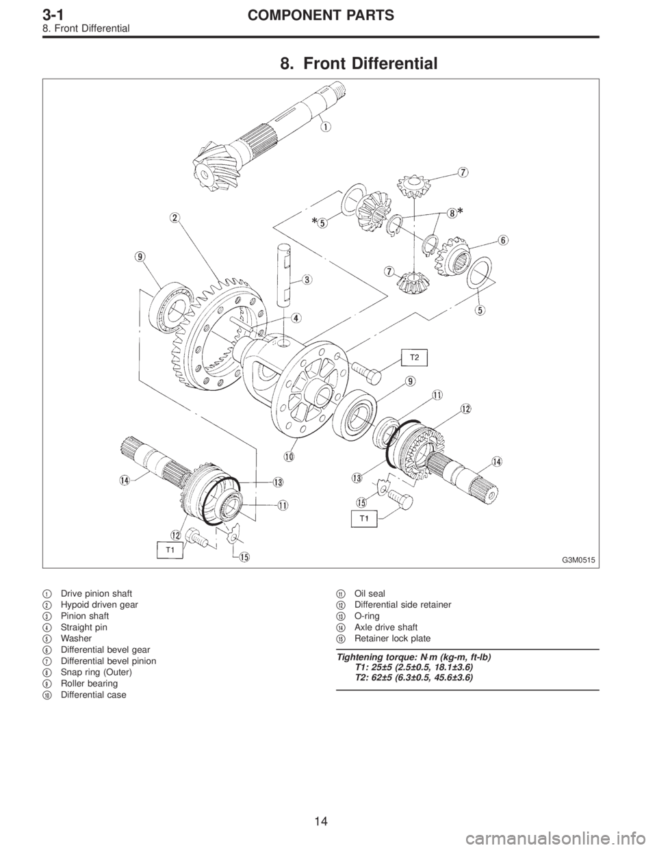
8. Front Differential
G3M0515
�1Drive pinion shaft
�
2Hypoid driven gear
�
3Pinion shaft
�
4Straight pin
�
5Washer
�
6Differential bevel gear
�
7Differential bevel pinion
�
8Snap ring (Outer)
�
9Roller bearing
�
10Differential case�
11Oil seal
�
12Differential side retainer
�
13O-ring
�
14Axle drive shaft
�
15Retainer lock plate
Tightening torque: N⋅m (kg-m, ft-lb)
T1: 25±5 (2.5±0.5, 18.1±3.6)
T2: 62±5 (6.3±0.5, 45.6±3.6)
14
3-1COMPONENT PARTS
8. Front Differential
Page 799 of 2890
 Install differential assembly�3on left hand transmission
case.
CAUTION:
Be careful not to fold the sealing lip of oil seal.
NOTE:
Wrap the left and right splined sections of axle shaft with")
G3M0557
3) Install differential assembly�3on left hand transmission
case.
CAUTION:
Be careful not to fold the sealing lip of oil seal.
NOTE:
Wrap the left and right splined sections of axle shaft with
vinyl tape to prevent scratches.
G3M0558
4) Install needle bearing and oil seal onto the front of
transmission main shaft assembly�
4, and position in left
side transmission case.
CAUTION:
�Wrap clutch splined section with vinyl tape to pre-
vent damage to oil seal.
�Apply grease (Unilube #2 or equivalent) to the seal-
ing lip of oil seal.
NOTE:
�Align the end face of seal with surface A of left side
transmission main case when installing oil seal.
�Be careful not to drop oil seal when installing right side
transmission main case.
�Make sure straight pin is positioned in hole in needle
bearing’s outer race.
G3M0575
5) Install drive pinion shaft assembly�5with shims
selected before into transmission case.
NOTE:
Ensure that the knock pin of the case is fitted into the hole
in the bearing outer race.
43
3-1SERVICE PROCEDURE
4. Transmission Case
Page 821 of 2890
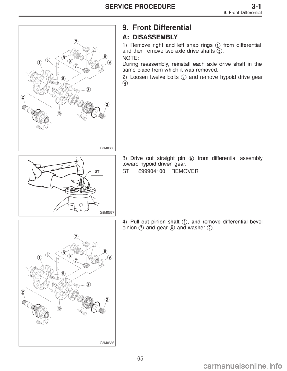
G3M0666
9. Front Differential
A: DISASSEMBLY
1) Remove right and left snap rings�1from differential,
and then remove two axle drive shafts�
2.
NOTE:
During reassembly, reinstall each axle drive shaft in the
same place from which it was removed.
2) Loosen twelve bolts�
3and remove hypoid drive gear
�
4.
G3M0667
3) Drive out straight pin�5from differential assembly
toward hypoid driven gear.
ST 899904100 REMOVER
G3M0666
4) Pull out pinion shaft�6, and remove differential bevel
pinion�
7and gear�8and washer�9.
65
3-1SERVICE PROCEDURE
9. Front Differential
Page 824 of 2890
B3M0100
6) Position drive axle shaft in differential case and hold it
with outer snap ring (28). Using a thickness gauge, mea-
sure clearance between the shaft and case is within speci-
fications.
Clearance:
0—0.2 mm (0—0.008 in)
If it is not within specifications, replace snap ring with a
suitable one.
Snap ring (Outer-28)
Part No. Thickness mm (in)
805028011 1.05 (0.0413)
805028012 1.20 (0.0472)
68
3-1SERVICE PROCEDURE
9. Front Differential
Page 850 of 2890
 Ensure the vehicle is in safe condition.
NOTE:
Do not check the oil level nor add oil to the case with the
front end of the vehicle jacked-up; this will resul")
G3M0283
2. DIFFERENTIAL GEAR OIL LEVEL
1) Ensure the vehicle is in safe condition.
NOTE:
Do not check the oil level nor add oil to the case with the
front end of the vehicle jacked-up; this will result in an
incorrect reading of the oil level.
2) Check whether the oil level is between the upper (F)
and lower (L) marks. If it is below the lower limit mark, add
oil until the level reaches the upper mark.
G3M0854
3. OIL LEAKAGE
It is difficult to accurately determine the precise position of
a oil leak, since the surrounding area also becomes wet
with oil. The places where oil seals and gaskets are used
are as follows:
Jointing portion of the case
�Transmission case and oil pump housing jointing portion
�Torque converter clutch case and oil pump housing joint-
ing portion
�Transmission case and transmission cover jointing por-
tion (FWD)
�Transmission case and extension case jointing portion
(AWD)
G3M0855
Torque converter clutch case
�Engine crankshaft oil seal
�Torque converter clutch impeller sleeve oil seal
�ATF cooler pipe connector
�Torque converter clutch
�Torque converter clutch case
�Axle shaft oil seal
�O-ring on the outside diameter of axle shaft oil seal
holder
�O-ring on the differential oil gauge
�Differential oil drain plug
�Speedometer cable mounting portion
�Location of steel balls
24
3-2SERVICE PROCEDURE
2. On-Car Services
![SUBARU LEGACY 1996 Service Repair Manual G2M0345
3. Fuel Tank
A: REMOVAL
1) Release fuel pressure. <Ref. to 2-8 [W1A0].>
2) Drain fuel from fuel tank. <Ref. to 2-8 [W1B0].>
G2M0382
3) Remove rear exhaust pipe.
(1) Lift-up the vehicle.
(2) Se](/manual-img/17/57433/w960_57433-561.png "SUBARU LEGACY 1996 Service Repair Manual G2M0345
3. Fuel Tank
A: REMOVAL
1) Release fuel pressure. <Ref. to 2-8 [W1A0].>
2) Drain fuel from fuel tank. <Ref. to 2-8 [W1B0].>
G2M0382
3) Remove rear exhaust pipe.
(1) Lift-up the vehicle.
(2) Se")
![SUBARU LEGACY 1996 Service Repair Manual G2M0345
3. Fuel Tank
A: REMOVAL
1) Release fuel pressure. <Ref. to 2-8 [W1A0].>
2) Drain fuel from fuel tank. <Ref. to 2-8 [W1B0].>
G2M0382
3) Remove rear exhaust pipe.
(1) Lift-up the vehicle.
(2) Se](/manual-img/17/57433/w960_57433-670.png "SUBARU LEGACY 1996 Service Repair Manual G2M0345
3. Fuel Tank
A: REMOVAL
1) Release fuel pressure. <Ref. to 2-8 [W1A0].>
2) Drain fuel from fuel tank. <Ref. to 2-8 [W1B0].>
G2M0382
3) Remove rear exhaust pipe.
(1) Lift-up the vehicle.
(2) Se")
 Position drive axle shaft in differential case and hold it
with outer snap ring (28). Using a thickness gauge, mea-
sure clearance between the shaft and case is within speci-
fications.
Cle")