Page 2052 of 2890

10AS1
CHECK OPERATION OF BRAKE LIGHT.
: Does brake light come on when depressing
the brake pedal?
: Go to step10AS2.
: Repair or replace brake light circuit.
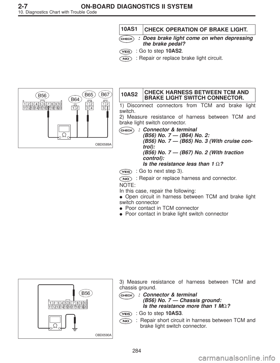
OBD0589A
10AS2CHECK HARNESS BETWEEN TCM AND
BRAKE LIGHT SWITCH CONNECTOR.
1) Disconnect connectors from TCM and brake light
switch.
2) Measure resistance of harness between TCM and
brake light switch connector.
: Connector & terminal
(B56) No. 7—(B64) No. 2:
(B56) No. 7—(B65) No. 3 (With cruise con-
trol):
(B56) No. 7—(B67) No. 2 (With traction
control):
Is the resistance less than 1Ω?
: Go to next step 3).
: Repair or replace harness and connector.
NOTE:
In this case, repair the following:
�Open circuit in harness between TCM and brake light
switch connector
�Poor contact in TCM connector
�Poor contact in brake light switch connector
OBD0590A
3) Measure resistance of harness between TCM and
chassis ground.
: Connector & terminal
(B56) No. 7—Chassis ground:
Is the resistance more than 1 MΩ?
: Go to step10AS3.
: Repair short circuit in harness between TCM and
brake light switch connector.
284
2-7ON-BOARD DIAGNOSTICS II SYSTEM
10. Diagnostics Chart with Trouble Code
Page 2302 of 2890

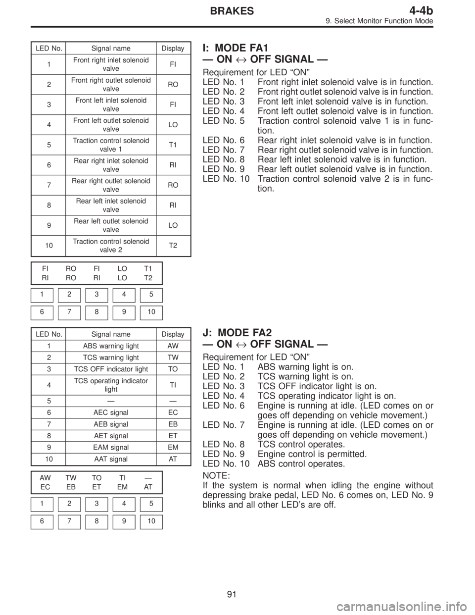
LED No. Signal name Display
1Front right inlet solenoid
valveFI
2Front right outlet solenoid
valveRO
3Front left inlet solenoid
valveFI
4Front left outlet solenoid
valveLO
5Traction control solenoid
valve 1T1
6Rear right inlet solenoid
valveRI
7Rear right outlet solenoid
valveRO
8Rear left inlet solenoid
valveRI
9Rear left outlet solenoid
valveLO
10Traction control solenoid
valve 2T2
FI RO FI LO T1
RI RO RI LO T2
1
2345
678910
I: MODE FA1
—ON↔OFF SIGNAL—
Requirement for LED“ON”
LED No. 1 Front right inlet solenoid valve is in function.
LED No. 2 Front right outlet solenoid valve is in function.
LED No. 3 Front left inlet solenoid valve is in function.
LED No. 4 Front left outlet solenoid valve is in function.
LED No. 5 Traction control solenoid valve 1 is in func-
tion.
LED No. 6 Rear right inlet solenoid valve is in function.
LED No. 7 Rear right outlet solenoid valve is in function.
LED No. 8 Rear left inlet solenoid valve is in function.
LED No. 9 Rear left outlet solenoid valve is in function.
LED No. 10 Traction control solenoid valve 2 is in func-
tion.
LED No. Signal name Display
1 ABS warning light AW
2 TCS warning light TW
3 TCS OFF indicator light TO
4TCS operating indicator
lightTI
5——
6 AEC signal EC
7 AEB signal EB
8 AET signal ET
9 EAM signal EM
10 AAT signal AT
AW TW TO TI—
EC EB ET EM AT
1
2345
678910
J: MODE FA2
—ON↔OFF SIGNAL—
Requirement for LED“ON”
LED No. 1 ABS warning light is on.
LED No. 2 TCS warning light is on.
LED No. 3 TCS OFF indicator light is on.
LED No. 4 TCS operating indicator light is on.
LED No. 6 Engine is running at idle. (LED comes on or
goes off depending on vehicle movement.)
LED No. 7 Engine is running at idle. (LED comes on or
goes off depending on vehicle movement.)
LED No. 8 TCS control operates.
LED No. 9 Engine control is permitted.
LED No. 10 ABS control operates.
NOTE:
If the system is normal when idling the engine without
depressing brake pedal, LED No. 6 comes on, LED No. 9
blinks and all other LED’s are off.
91
4-4bBRAKES
9. Select Monitor Function Mode
Page 2747 of 2890
ABBREVIATION LIST
Abbr. Full name
A.B.S. Antilock Brake System
ACC Accessory
A/C Air Conditioning
AD Auto Down
AT Automatic Transmission
AU Auto Up
+B Battery
DN Down
DRL Daytime Running Light
E Ground
F/B Fuse & Joint Box
FL1.5 Fusible link 1.5 mm
2
IG Ignition
Illumi. Illumination
Abbr. Full name
LH Left Hand
Lo Low
M Motor
M/B Main Fuse Box
MG Magnet
Mi Middle
OP Optional Parts
PASS Passing
RH Right Hand
SBF Slow Blow Fuse
S.M.J. Super Multiple Junction
ST Starter
SW Switch
T.C.S. Traction Control System
UP Up
WASH Washer
17
6-3WIRING DIAGRAM
5. How to Use Super Multiple Junction (S.M.J.)
Page 2832 of 2890
34. TRACTION CONTROL SYSTEM
BU100-02A
102
6-3WIRING DIAGRAM
6. Wiring Diagram