Page 1015 of 2890
 Position vehicle on a level surface.
2) Move vehicle 3 to 4 meters directly forward.
3) Determine locus of both front and rear axles.
4) Measure distance“L”b")
G4M0488
6. THRUST ANGLE
�Inspection
1) Position vehicle on a level surface.
2) Move vehicle 3 to 4 meters directly forward.
3) Determine locus of both front and rear axles.
4) Measure distance“L”between center line of loci of the
axles.
Thrust angle is less than 20’when“L”is equal to or less
than 15 mm (0.59 in).
�Adjustment
Make thrust angle adjustments by turning toe-in adjusting
bolts of rear suspension equally in the same direction.
NOTE:
On FWD models, turn adjusting wheels one by one, by the
some amount in the opposite direction of the adjusting
bolts.
When one rear wheel is adjusted in a toe-in direction,
adjust the other rear wheel equally in toe-out direction, in
order to make thrust angle adjustment.
When left and right adjusting bolts are turned incremen-
tally by one graduation in the same direction, the thrust
angle of the AWD model will change approximately 10’[“L”
is almost equal to 7.5 mm (0.295 in)] and the thrust angle
of the FWD model will change approximately 12’[“L”is
almost equal to 9 mm (0.35 in)].
Thrust angle:
0°±20′
B4M0193A
NOTE:
Thrust angle refers to a mean value of left and right rear
wheel toe angles in relation to vehicle body center line.
Vehicle is driven straight in the thrust angle direction while
swinging in the oblique direction depending on the degree
of the mean thrust angle.
B4M0194A
Thrust angle: r
r=α�β2
α: Right rear wheel toe angle
β: Left rear wheel toe angle
NOTE:
Here, use only positive toe-in values from each wheel to
substitute forαandβin the equation.
14
4-1SERVICE PROCEDURE
1. On-car Services
Page 1031 of 2890
G4M0524
B: DISASSEMBLY
1. FRONT BUSHING
Using ST, press front bushing out of place.
ST 927720000 INSTALLER & REMOVER SET
G4M0525
2. REAR BUSHING
1) Remove housing. Refer to“4-2 WHEELS AND AXLES”
for removal procedures.
2) Using ST, press rear bushing out of place.
ST 927730000 INSTALLER & REMOVER SET
C: INSPECTION
Check trailing links for bends, corrosion or damage.
30
4-1SERVICE PROCEDURE
7. Rear Trailing Link
Page 1049 of 2890
G4M0208
1. Wheels and Axles
A: SPECIFICATIONS
1. TIRE AND WHEEL SIZE
Tire size Rim sizeRim offset
mm (in)P.C.D.
mm (in)
Except OUTBACK modelFront and RearP185/70R14
87S14×5 1/2JJ 55 (2.17)
100 (3.94)
dia. P195/60R15
87H15 x 6JJ 55 (2.17)
T-type tireT125/70D15 15 x 4T 53 (2.09)
T135/70D16 16 x 4T 50 (1.97)
OUTBACK modelFront and RearP205/70R15
95S15 x 6JJ 55 (2.17)
T-type tire T135/80D16 16 x 4T 50 (1.97)
NOTE:“T-type”tire for temporary use is supplied as a spare tire.
2. TIRE INFLATION PRESSURE
Tire sizeTire inflation pressure kPa (kg/cm
2, psi)
Light load Full load Trailler towing
Except OUTBACK
modelFront and RearP185/70R14 87S
P195/60R15 87HFt: 220 (2.2, 32)
Rr: 210 (2.1, 30)—
T-type tireT125/70D15
T135/70D16420 (4.2, 60)
OUTBACK modelFront and Rear P205/70R15 95SFt: 200 (2.0, 29)
Rr: 190 (1.9, 28)Ft: 200 (2.0, 2.9)
Rr: 220 (2.2, 32)
T-type tire T135/80D16 420 (4.2, 60)
2
4-2SPECIFICATIONS AND SERVICE DATA
1. Wheels and Axles
Page 1050 of 2890
3. FRONT DRIVE SHAFT ASSEMBLY
Type of drive
shaft assemblySHAFT DOJ FTJ
No. of
identification
paddings on
shaftNo. of spline
teethNo. of spline
teeth
87AC-DOJ 1 (One) 25—
87AC-FTJ 0 (None)—25
95AC-DOJ 3 (Three) 25—
B4M0772A
4. REAR DRIVE SHAFT ASSEMBLY (AWD MODEL)
Type of drive shaft assemblySHAFT
No. of identification paddings on shaft
79AC-RH 1 (One)
79AC-LH 1 (One)
B4M0547A
3
4-2SPECIFICATIONS AND SERVICE DATA
1. Wheels and Axles
Page 1051 of 2890
5. APPLICATION TABLE
Model Power unitFront drive shaft
Rear drive shaft
5MT 4AT
FWD 2200 cc 95AC-DOJ 87AC-DOJ—
AWD 2200 cc 87AC-DOJ 87AC-DOJ 79AC-RH, 79AC-LH
AWD 2500 cc—87AC-FTJ 79AC-RH, 79AC-LH
B: SERVICE DATA
Wheel balancing Standard Service limit
Dynamic unbalance Less than 5 g (0.18 oz)
Balance weight part number
(For steel wheel)Weight g (oz)
28101AA001 5 (0.18)
28101AA011 10 (0.35)
28101AA021 15 (0.53)
28101AA031 20 (0.71)
28101AA041 25 (0.88)
28101AA051 30 (1.06)
28101AA061 35 (1.23)
28101AA071 40 (1.41)
28101AA081 45 (1.59)
28101AA091 50 (1.76)
28101AA101 55 (1.94)
28101AA111 60 (2.12)
Balance weight part number
(For aluminum wheel)Weight g (oz)
23141GA462 5 (0.18)
23141GA472 10 (0.35)
23141GA482 15 (0.53)
23141GA492 20 (0.71)
23141GA502 25 (0.88)
23141GA512 30 (1.06)
23141GA522 35 (1.23)
23141GA532 40 (1.41)
23141GA542 45 (1.59)
23141GA552 50 (1.76)
—55 (1.94)
23141GA572 60 (2.12)
4
4-2SPECIFICATIONS AND SERVICE DATA
1. Wheels and Axles
Page 1052 of 2890
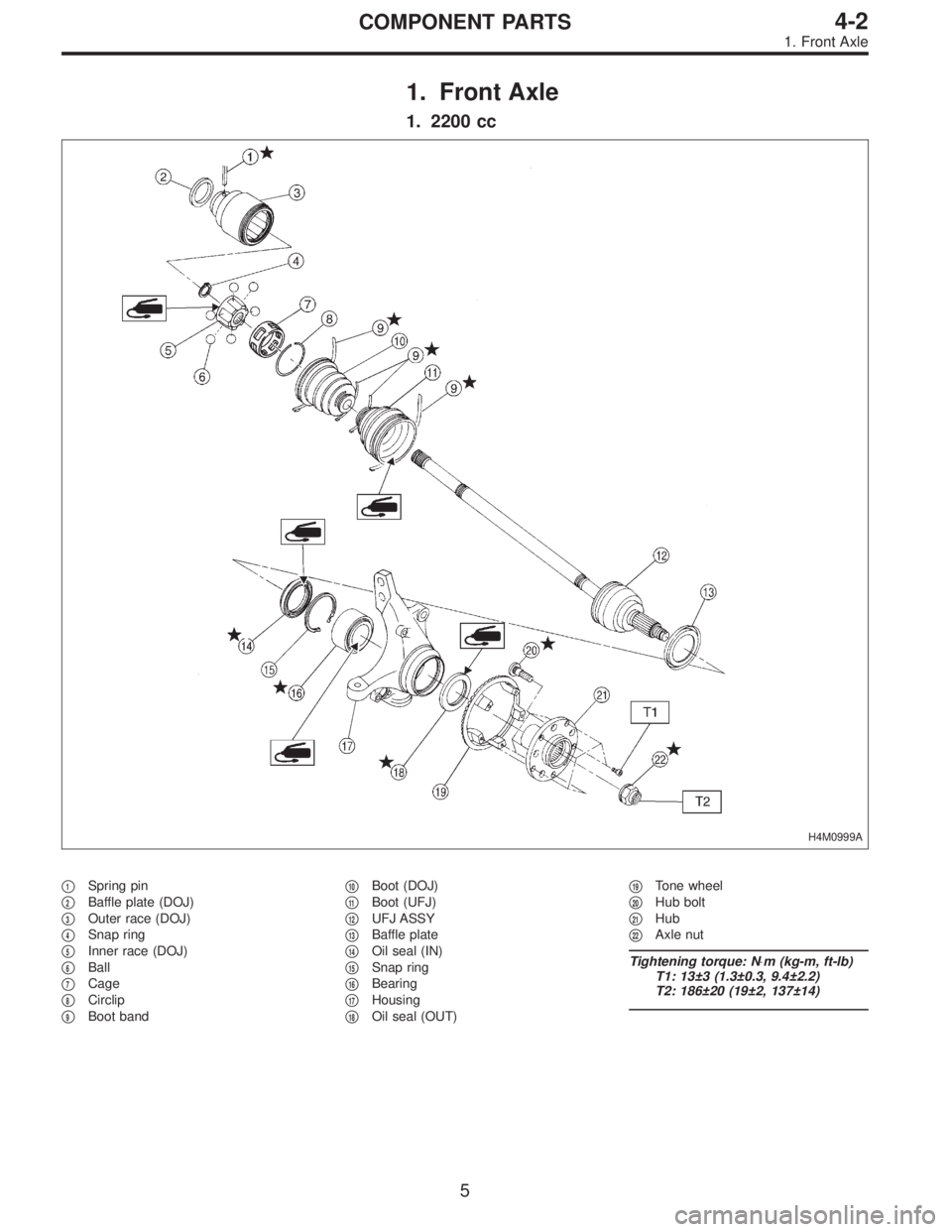
1. Front Axle
1. 2200 cc
H4M0999A
�1Spring pin
�
2Baffle plate (DOJ)
�
3Outer race (DOJ)
�
4Snap ring
�
5Inner race (DOJ)
�
6Ball
�
7Cage
�
8Circlip
�
9Boot band�
10Boot (DOJ)
�
11Boot (UFJ)
�
12UFJ ASSY
�
13Baffle plate
�
14Oil seal (IN)
�
15Snap ring
�
16Bearing
�
17Housing
�
18Oil seal (OUT)�
19Tone wheel
�
20Hub bolt
�
21Hub
�
22Axle nut
Tightening torque: N⋅m (kg-m, ft-lb)
T1: 13±3 (1.3±0.3, 9.4±2.2)
T2: 186±20 (19±2, 137±14)
5
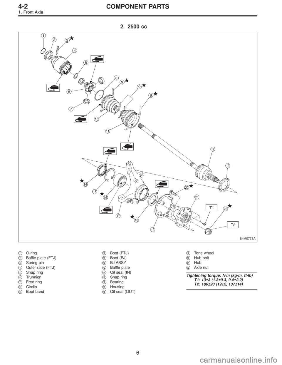
4-2COMPONENT PARTS
1. Front Axle
Page 1053 of 2890
2. 2500 cc
B4M0773A
�1O-ring
�
2Baffle plate (FTJ)
�
3Spring pin
�
4Outer race (FTJ)
�
5Snap ring
�
6Trunnion
�
7Free ring
�
8Circlip
�
9Boot band�
10Boot (FTJ)
�
11Boot (BJ)
�
12BJ ASSY
�
13Baffle plate
�
14Oil seal (IN)
�
15Snap ring
�
16Bearing
�
17Housing
�
18Oil seal (OUT)�
19Tone wheel
�
20Hub bolt
�
21Hub
�
22Axle nut
Tightening torque: N⋅m (kg-m, ft-lb)
T1: 13±3 (1.3±0.3, 9.4±2.2)
T2: 186±20 (19±2, 137±14)
6
4-2COMPONENT PARTS
1. Front Axle
Page 1056 of 2890
1. Front Axle
A: REMOVAL
1) Disconnect ground cable from battery.
2) Jack-up vehicle, support it with safety stands, and
remove front wheels.
G4M0214
3) Unlock axle nut.
4) Remove axle nut using a socket wrench.
CAUTION:
Be sure to loose and retighten axle nut after removing
wheel from vehicle. Failure to follow this rule may dam-
age wheel bearings.
G4M0215
5) Remove stabilizer link.
G4M0216
6) Remove DOJ from transmission spindle.
7) Remove front drive shaft assembly from hub. If it is hard
to remove, use STs.
ST1 926470000 AXLE SHAFT PULLER
ST2 927140000 PLATE
CAUTION:
�Be careful not to damage oil seal lip when removing
front drive shaft.
�When replacing front drive shaft, also replace inner
oil seal.
8) Remove disc brake caliper from housing, and suspend
it from strut using a wire.
9
4-2SERVICE PROCEDURE
1. Front Axle
 Remove housing. Refer to“4-2 WHEELS AND AXLES”
f")
P.C.D.
mm (in)
Except OUTBACK modelFront and RearP185/70R14
87S14×5 1/2JJ 55 (2.17)
100 (3.94)")
 25—
87AC-FTJ 0 (None)—25
95AC")

 Disconnect ground cable from battery.
2) Jack-up vehicle, support it with safety stands, and
remove front wheels.
G4M0214
3) Unlock axle nut.
4) Remove axle nut using a soc")