Page 16 of 2890

SERVICE
PROCEDURE
7
.
Combination
Switch
8)
Remove
steering
column
cowers
.
9)
Removing
two
retaining
screws,
remove
combination
switch
.
B
:
ADJUSTMENT
1
.
CENTERING
ROLL
CONNECTOR")
5-5b
[W7B1)
SERVICE
PROCEDURE
7
.
Combination
Switch
8)
Remove
steering
column
cowers
.
9)
Removing
two
retaining
screws,
remove
combination
switch
.
B
:
ADJUSTMENT
1
.
CENTERING
ROLL
CONNECTOR
Before
installing
steering
wheel,
make
sure
to
center
roil
connector
built
into
combination
switch
.
1)
Make
sure
that
front
wheels
are
positioned
straight
ahead
.
2)
Install
steering
gearbox,
steering
shaft
and
combina-
tion
switchproperly
.
Turn
roll
connector
pin
(J)
clockwise
until
it
stops
.
3)
Then,
back
off
roll
connector
pin
1~
approximately
2
.65
turns
until
"A"
marks
aligned
.
C
:
INSTALLATION
1)
Before
installing
combination
switch,
check
to
ensure
that
combination
switch
is
off
and
font
wheels
are
set
in
the
.straight
ahead
position
.
CAUTION
:
Failure
to
do
this
might
damage
roll
connoctok
.
2)
Install
column
cover
and
center
roll
connector
.
3)
Install
steering
wheel
in
neutral
position
.
Carefully
insert
roll
connector
pin
1(~
into
hole
on
steering
wheel
.
NOTE
:
If
steering
wheel
angle
requires
fine
adjustment,
adjust
tie-rod
.
<
Ref
.
to
4-3
[W3FOj
.*1
>
4)
Install
airbag
module
and
lower
cover
in
the
reverse
order
of
removal
.
6
Page 1012 of 2890
 Loosen the left and right side steering tie-rods lock nuts.
2) Turn the left and right tie rods equal amounts until the
toe-in is at the specification.
Both the left and right t")
G4M0482
�Adjustment
1) Loosen the left and right side steering tie-rods lock nuts.
2) Turn the left and right tie rods equal amounts until the
toe-in is at the specification.
Both the left and right tie-rods are right-hand threaded. To
increase toe-in, turn both tie-rods clockwise equal amounts
(as viewed from the inside of the vehicle).
3) Tighten tie-rod lock nut.
Tightening torque:
83±5 N⋅m (8.5±0.5 kg-m, 61.5±3.6 ft-lb)
CAUTION:
Correct tie-rod boot, if it is twisted.
NOTE:
Check the left and right wheel steering angle is within
specifications.
M4A0059
4. REAR WHEEL TOE-IN (FWD MODEL)
�Inspection
1) Using a toe-in gauge, measure rear wheel toe-in.
Toe-in: 0±3 mm (0±0.12 in)
2) Mark rear sides of left and right tires at height corre-
sponding to center of spindles and measure distance“B”
between marks.
3) Move vehicle forward so that marks line up with front
sides at height corresponding to center of spindles.
4) Measure distance“A”between left and right marks.
Toe-in can then be obtained by the following equation:
B�A = Toe-in
G4M0483
�Adjustment
1) Remove cap from lateral link and loosen self-locking
nut.
CAUTION:
�When loosening or tightening adjusting bolt, hold
the bolt head and loosen self-locking nut.
�Replace self-locking nut with a new one.
2) Using two wrenches, turn adjusting wheel and adjusting
bolt equally in opposite directions so that toe-in is at the
specification.
11
4-1SERVICE PROCEDURE
1. On-car Services
Page 1016 of 2890
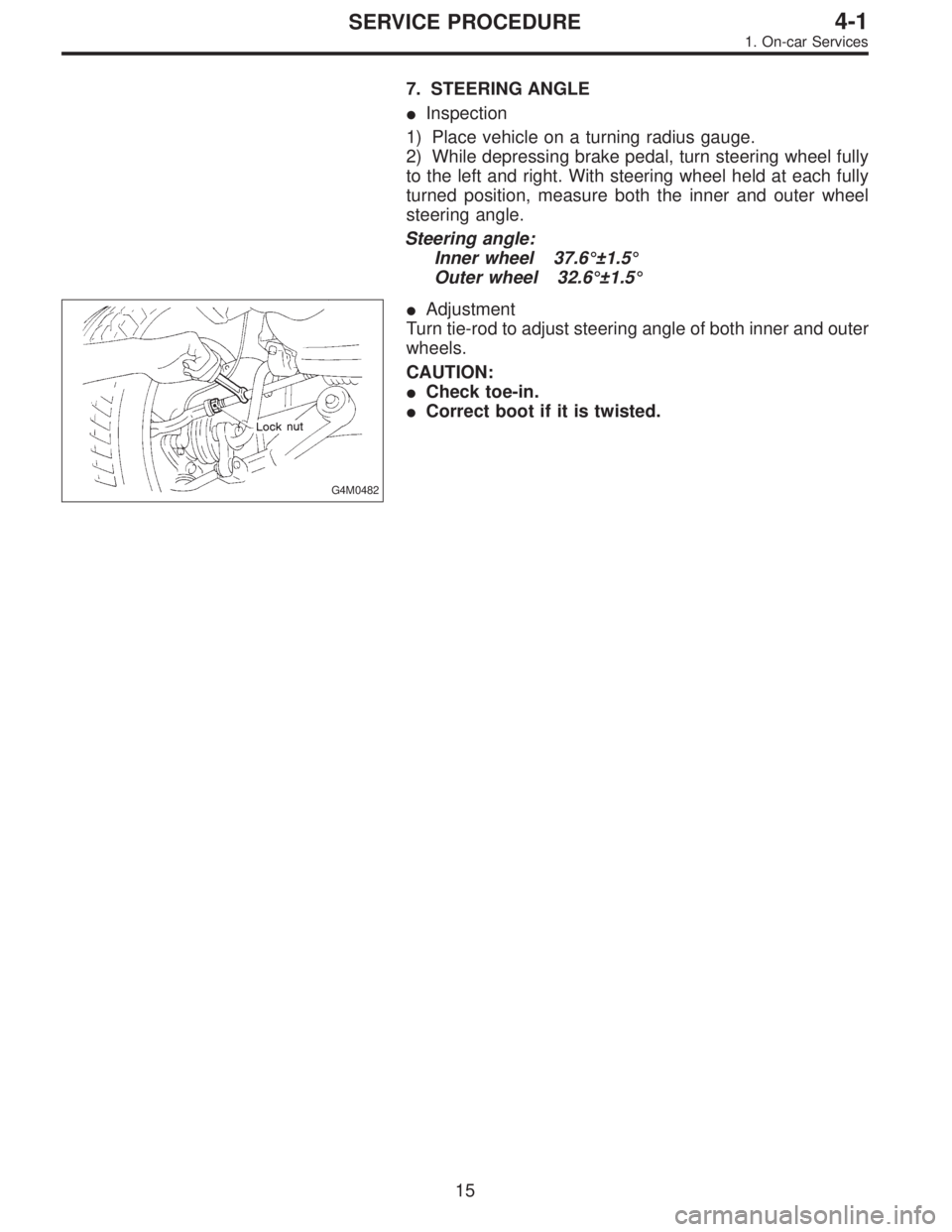
7. STEERING ANGLE
�Inspection
1) Place vehicle on a turning radius gauge.
2) While depressing brake pedal, turn steering wheel fully
to the left and right. With steering wheel held at each fully
turned position, measure both the inner and outer wheel
steering angle.
Steering angle:
Inner wheel 37.6°±1.5°
Outer wheel 32.6°±1.5°
G4M0482
�Adjustment
Turn tie-rod to adjust steering angle of both inner and outer
wheels.
CAUTION:
�Check toe-in.
�Correct boot if it is twisted.
15
4-1SERVICE PROCEDURE
1. On-car Services
Page 1131 of 2890
![SUBARU LEGACY 1996 Service Repair Manual �Make adjustment so that steering wheel can be rotated
fully from lock to lock without binding.
9) Check for service limit as per article of“Service limit”.
<Ref. to 4-3 [W3C1].> Make replacement](/manual-img/17/57433/w960_57433-1130.png "SUBARU LEGACY 1996 Service Repair Manual �Make adjustment so that steering wheel can be rotated
fully from lock to lock without binding.
9) Check for service limit as per article of“Service limit”.
<Ref. to 4-3 [W3C1].> Make replacement")
�Make adjustment so that steering wheel can be rotated
fully from lock to lock without binding.
9) Check for service limit as per article of“Service limit”.
Make replacement and adjustment
if necessary.
10) Install boot and mounting rubber to housing.
NOTE:
Apply grease through small hole in boot.
G4M0123
11) Fit clip (large) to boot, and then install boot to gearbox
while holding boot flange.
After installing boot, fold back boot flange to the extent that
large clip can not be seen.
NOTE:
�Before installing boot, be sure to apply grease to the
groove of tie-rod.
�Install fitting portions of boots to the following portions in
both sides of assembled steering gearbox.
1. The groove on gearbox
2. The groove on the rod
�Make sure that boot is installed without unusual inflation
or deflation.
G4M0124
12) Turn boot until it seats well on gearbox and rubber
mounting, then bend boot flange back.
G4M0125
13) Fix boot end with clip (small).
CAUTION:
Use screwdriver with blunted tip to prevent boot from
damage, when installing.
NOTE:
After installing, check boot end is positioned into groove on
tie-rod.
24
4-3SERVICE PROCEDURE
3. Steering Gearbox (Power Steering System) [LHD model]
Page 1134 of 2890
G4M0132
15) After adjusting toe-in and steering angle, tighten lock
nut on tie-rod end.
Tightening torque:
83±5 N⋅m (8.5±0.5 kg-m, 61.5±3.6 ft-lb)
CAUTION:
When adjusting toe-in, hold boot as shown to prevent
it from being rotated or twisted. If twisted, straighten it.
G4M0133
F: ADJUSTMENT
1) Adjust front toe.
Standard of front toe:
IN 3—OUT 3 mm (IN 0.12—OUT 0.12 in)
2) Adjust steering angle of wheels.
Inner wheel: 37.6°±1.5
Outer wheel: 32.6°±1.5
B4M0133A
3) If steering wheel spokes are not horizontal when wheels
are set in the straight ahead position, and error is more
than 5°on the periphery of steering wheel, correctly re-in-
stall the steering wheel.
G4M0135
4) If steering wheel spokes are not horizontal with vehicle
set in the straight ahead position after this adjustment,
correct it by turning the right and left tie-rods in the same
direction by the same turns.
27
4-3SERVICE PROCEDURE
3. Steering Gearbox (Power Steering System) [LHD model]
Page 1146 of 2890
2) Adjust steering angle of wheels.
Standard of steering angle:
Inner wheel 37.6°±1.5°
Outer wheel 32.6°±1.5°
B4M0133A
3) If steering wheel spokes are not horizontal when wheels
are set in the straight ahead position, and error is more
than 5°on the periphery of steering wheel, correctly re-in-
stall the steering wheel.
G4M0135
4) If steering wheel spokes are not horizontal with vehicle
set in the straight ahead position after this adjustment,
correct it by turning the right and left tie-rods in the same
direction by the same amount.
39
4-3SERVICE PROCEDURE
4. Steering Gearbox (Power Steering System) [RHD model]
Page 1147 of 2890
![SUBARU LEGACY 1996 Service Repair Manual 5. Control Valve (Power Steering
Gearbox) [LHD model]
NOTE:
This section focuses on the disassembly and reassembly
of control valve. For the inspection and adjustment and the
service procedures for as](/manual-img/17/57433/w960_57433-1146.png "SUBARU LEGACY 1996 Service Repair Manual 5. Control Valve (Power Steering
Gearbox) [LHD model]
NOTE:
This section focuses on the disassembly and reassembly
of control valve. For the inspection and adjustment and the
service procedures for as")
5. Control Valve (Power Steering
Gearbox) [LHD model]
NOTE:
This section focuses on the disassembly and reassembly
of control valve. For the inspection and adjustment and the
service procedures for associated parts, refer to“Steering
Gearbox”.
G4M0136
�1Power cylinder
�
2Cylinder
�
3Rack piston
�
4Rack axle
�
5Input shaft�
6Torsion bar
�
7Valve housing
�
8Valve body
�
9Control valve�
10Pipe B
�
11Pipe A
�
12Pinion
�
13Pinion axle
A: CHECKING OIL LEAKING POINTS
1. OIL LEAKING POINTS
1) If leak point is other than a, b, c, or d, perform check
step 5) in 4-3 [W5A2] before dismounting gearbox from
vehicle. If gearbox is dismounted without confirming where
the leak is, it must be mounted again to locate the leak
point.
2) Even if the location of the leak can be easily found by
observing the leaking condition, it is necessary to thor-
oughly remove the oil from the suspected portion and turn
the steering wheel from lock to lock about 30 to 40 times
with engine running, then make comparison of the sus-
pected portion between immediately after and several
hours after this operation.
3) Before starting oil leak repair work, be sure to clean the
gearbox, hoses, pipes, and surrounding parts. After com-
pleting repair work, clean these areas again.
40
4-3SERVICE PROCEDURE
5. Control Valve (Power Steering Gearbox) [LHD model]
Page 1156 of 2890
![SUBARU LEGACY 1996 Service Repair Manual 6. Control Valve (Power Steering
Gearbox) [RHD model]
NOTE:
This section focuses on the disassembly and reassembly
of control valve. For the inspection and adjustment and the
service procedures for as](/manual-img/17/57433/w960_57433-1155.png "SUBARU LEGACY 1996 Service Repair Manual 6. Control Valve (Power Steering
Gearbox) [RHD model]
NOTE:
This section focuses on the disassembly and reassembly
of control valve. For the inspection and adjustment and the
service procedures for as")
6. Control Valve (Power Steering
Gearbox) [RHD model]
NOTE:
This section focuses on the disassembly and reassembly
of control valve. For the inspection and adjustment and the
service procedures for associated parts, refer to“Steering
Gearbox”.
B4M0668A
A: CHECKING OIL LEAKING POINTS
1. OIL LEAKING POINTS
1) If leak point is other than a, b, c, or d, perform check
step 5) in 4-3 [W6A2] before dismounting gearbox from
vehicle. If gearbox is dismounted without confirming where
the leak is, it must be mounted again to locate the leak
point.
2) Even if the location of the leak can be easily found by
observing the leaking condition, it is necessary to thor-
oughly remove the oil from the suspected portion and turn
the steering wheel from lock to lock about 30 to 40 times
with engine running, then make comparison of the sus-
pected portion between immediately after and several
hours after this operation.
3) Before starting oil leak repair work, be sure to clean the
gearbox, hoses, pipes, and surrounding parts. After com-
pleting repair work, clean these areas again.
49
4-3SERVICE PROCEDURE
6. Control Valve (Power Steering Gearbox) [RHD model]
 After adjusting toe-in and steering angle, tighten lock
nut on tie-rod end.
Tightening torque:
83±5 N⋅m (8.5±0.5 kg-m, 61.5±3.6 ft-lb)
CAUTION:
When adjusting toe-in, hold boot as sho")
 Adjust steering angle of wheels.
Standard of steering angle:
Inner wheel 37.6°±1.5°
Outer wheel 32.6°±1.5°
B4M0133A
3) If steering wheel spokes are not horizontal when wheels
are set in the s")