Page 1162 of 2890

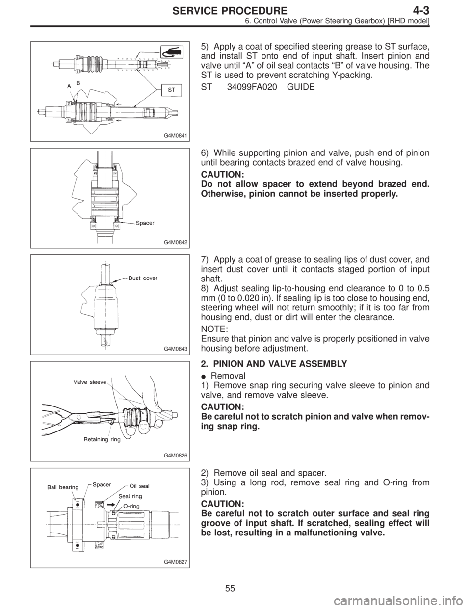
G4M0841
5) Apply a coat of specified steering grease to ST surface,
and install ST onto end of input shaft. Insert pinion and
valve until“A”of oil seal contacts“B”of valve housing. The
ST is used to prevent scratching Y-packing.
ST 34099FA020 GUIDE
G4M0842
6) While supporting pinion and valve, push end of pinion
until bearing contacts brazed end of valve housing.
CAUTION:
Do not allow spacer to extend beyond brazed end.
Otherwise, pinion cannot be inserted properly.
G4M0843
7) Apply a coat of grease to sealing lips of dust cover, and
insert dust cover until it contacts staged portion of input
shaft.
8) Adjust sealing lip-to-housing end clearance to 0 to 0.5
mm (0 to 0.020 in). If sealing lip is too close to housing end,
steering wheel will not return smoothly; if it is too far from
housing end, dust or dirt will enter the clearance.
NOTE:
Ensure that pinion and valve is properly positioned in valve
housing before adjustment.
G4M0826
2. PINION AND VALVE ASSEMBLY
�Removal
1) Remove snap ring securing valve sleeve to pinion and
valve, and remove valve sleeve.
CAUTION:
Be careful not to scratch pinion and valve when remov-
ing snap ring.
G4M0827
2) Remove oil seal and spacer.
3) Using a long rod, remove seal ring and O-ring from
pinion.
CAUTION:
Be careful not to scratch outer surface and seal ring
groove of input shaft. If scratched, sealing effect will
be lost, resulting in a malfunctioning valve.
55
4-3SERVICE PROCEDURE
6. Control Valve (Power Steering Gearbox) [RHD model]
Page 1592 of 2890
H5M0664
6) Disconnect airbag connector on back of airbag module.
Remove airbag module, and place it
with pad side facing upward.
G5M0332
7) Using steering puller, remove steering wheel.
CAUTION:
Do not allow connector to interfere when removing
steering wheel.
B5M0106
8) Remove steering column covers.
9) Removing two retaining screws, remove combination
switch.
B: ADJUSTMENT
1. CENTERING ROLL CONNECTOR
Before installing steering wheel, make sure to center roll
connector built into combination switch.
1) Make sure that front wheels are positioned straight
ahead.
2) Install steering gearbox, steering shaft and combination
switch properly. Turn roll connector pin�
1clockwise until
it stops.
H5M0663A
3) Then, back off roll connector pin�1approximately 2.65
turns until“�”marks aligned.
19
5-5SERVICE PROCEDURE
7. Combination Switch
Page 1593 of 2890
H5M0663A
C: INSTALLATION
1) Before installing combination switch, check to ensure
that combination switch is off and front wheels are set in
the straight ahead position.
CAUTION:
Failure to do this might damage roll connector.
2) Install column cover and center roll connector.
3) Install steering wheel in neutral position. Carefully insert
roll connector pin�
1into hole on steering wheel.
NOTE:
If steering wheel angle requires fine adjustment, adjust tie-
rod.
4) Install airbag module and lower cover in the reverse
order of removal.
20
5-5SERVICE PROCEDURE
7. Combination Switch
Page 1613 of 2890
H5M0664
6) Disconnect airbag connector on back of airbag module.
Remove airbag module, and place it
with pad side facing upward.
G5M0332
7) Using steering puller, remove steering wheel.
CAUTION:
Do not allow connector to interfere when removing
steering wheel.
B5M0106
8) Remove steering column covers.
9) Removing two retaining screws, remove combination
switch.
B: ADJUSTMENT
1. CENTERING ROLL CONNECTOR
Before installing steering wheel, make sure to center roll
connector built into combination switch.
1) Make sure that front wheels are positioned straight
ahead.
2) Install steering gearbox, steering shaft and combination
switch properly. Turn roll connector pin�
1clockwiseuntil
it stops.
H5M0663A
3) Then, back off roll connector pin�1approximately 2.65
turns until“�”marks aligned.
17
5-5bSERVICE PROCEDURE
6. Combination Switch
Page 1614 of 2890
H5M0663A
C: INSTALLATION
1) Before installing combination switch, check to ensure
that combination switch is off and front wheels are set in
the straight ahead position.
CAUTION:
Failure to do this might damage roll connector.
2) Install column cover and center roll connector.
3) Install steering wheel in neutral position. Carefully insert
roll connector pin�
1into hole on steering wheel.
NOTE:
If steering wheel angle requires fine adjustment, adjust tie-
rod.
4) Install airbag module and lower cover in the reverse
order of removal.
18
5-5bSERVICE PROCEDURE
6. Combination Switch