Page 18 of 2890
![SUBARU LEGACY 1996 Service Repair Manual
ON-BOARD
DIAGNOSTICS
II
SYSTEM
[Tiq2]
2-
1
.
General
1~
Engine
control
module
(ECM)
~
Radiator
fan
~2
Ignition
coil~s
Radiator
fan
relay
~3
Ignitqr
~s
Pressure
sources
switching
solenoid
valve
~ SUBARU LEGACY 1996 Service Repair Manual
ON-BOARD
DIAGNOSTICS
II
SYSTEM
[Tiq2]
2-
1
.
General
1~
Engine
control
module
(ECM)
~
Radiator
fan
~2
Ignition
coil~s
Radiator
fan
relay
~3
Ignitqr
~s
Pressure
sources
switching
solenoid
valve
~](/manual-img/17/57433/w960_57433-17.png)
ON-BOARD
DIAGNOSTICS
II
SYSTEM
[Tiq2]
2-
1
.
General
1~
Engine
control
module
(ECM)
~
Radiator
fan
~2
Ignition
coil~s
Radiator
fan
relay
~3
Ignitqr
~s
Pressure
sources
switching
solenoid
valve
~4
Crankshaft
position
sensor
~
Knock
sensor
~5
Camshaft
position
sensor
~
Back-pressure
transducer
Throttle
position
sensor
~s
Front
oxygen
sensor
~7
duel
injectors
~o
Rear
oxygen
sensor
(Except
California
model)
~8
Pressure
regulator
~
Pressure
sensor
Engine
coolant
temperature
sensor
~z
A/C
compressor
~o
Mass
air
flow
sensor
~
Inhibitor
switch
Idle
air
control
solenoid
valve
~
CHECK
ENGINE
malfunction
indicator
lamp
(MIL)
~z
Purge
control
solenoid
valve
~
Tachometer
0
Fuel
pump
~s
A/C
relay
0
PCV
valve
~
A/C
control
module
~s
Air
cleaner
~eIgnition
switch
Canister
~
Transmission
control
module
(TCM)
~
Main
relay
~o
Vehicle
speed
sensor
2
~a
Fuel
pump
relay
~
Data
link
connector
(For
Subaru
select
monitor)
~s
Fuel
filter
@
Data
link
connector
(For
Subaru
select
monitor
and
~o
Front
catalytic
converter
OBD-II
general
scan
tool)
Rear
catalytic
converter
@
Two
way
valve
~2
MGR
valve
~a
Rear
oxygen
sensor
(California
model
only)
EGR
control
solenoid
valve
~
Filter
3
Page 63 of 2890
2-7
[rsai]
ON-BOARD
DIAGNOSTICS
II
SYSTEM
6
.
Wiring
Diagram
and
Wiring
Harness
Engine
Shield
Boost
Throttle
coolant
joint
sensorposition
Knock
temperature
E
.G.R
.
connector
sensor
sensor
sensor
solenoid
BB3
FF
R
I
B2
H
I
(
:
P
P
(:
9
)
PEE
(
ED
EH
(
9
)
....
E2
821
Ref
.
toAT
control
system
.
Enginecontro
I
B84
module
....
822
E3
B3
Mess
air
flowsensor
.
.
..
..
..
III
(Ca
I
(forn
(a
mode
I)
arri
813
m
EE
Ignitor
O
(Brown)
El8
E8
(Brown)
(B
I
eck)
B2
El3
(Brown)
12
123
B3
(Grey)(
ED
(Grey)
1234
123456
52
Ell
(Gray)
123
B2l
(L
i
ght
gray)
1234
5678
910U12
Ell
Ignition
coil
B83
1234
B22
CL
i
ght
gray)
1234
5678
9
1011
12
13141516
BUR10-02C
Page 66 of 2890

ON-BOARD
DIAGNOSTICS
II
SYSTEM
[Tsn2i
2-7
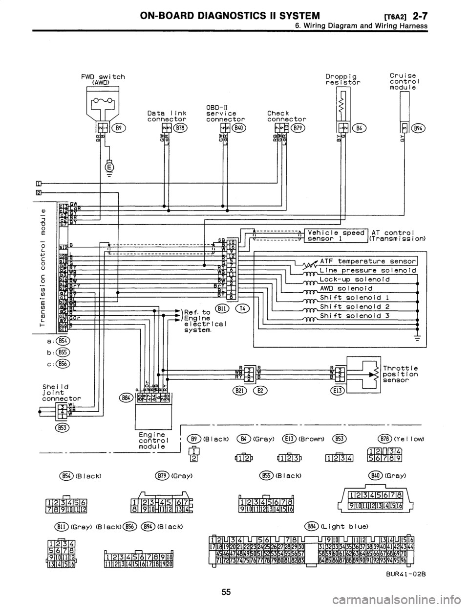
6
.
Wiring
Diagram
and
Wiring
Harness
FWD
switch
(AWD)
B9
ffl
Droppig
Cruise
resistor
cont
rol
modu
le
OBD-II
Data
link
serviceCheck
connectorconnectorconnector
B78
ERB40
0
B79
m
B4
E
K
E
)
w
7
OEs
o
-
-
-
------------------
-
------
-
-
L
a
....
c
H
0
U
It
C
Y
0
.N
;W
Rr
06
N
BI1
T41
Ref
.
to
/Engine
electrical
system
.
a
:
B54
b
:
B55
c
:
856
She
ild
joint
connector
884
~
WK
LZIM
WL
B53
Engine
control
B9(B
I
ac
k)
module
1
2
854
(B
I
ac
k)
B79
(Grey)
1
23456
1
23
45
67
7
1
8
1
9101112
8
910
1112
1
13
1
14
r,
Bll
(Grey)
(B
I
ac
k)
B56894
(B
I
aCk)
34
S
78
D
q
Oil
2
9
Pl
.
12131415,91617
la19
110
I
5
16
1
3
14
1111121131141151161171161191201
AT
contro
I
------------
a
,,
Vehicle
speed
i(Transmission)
___
_____
__
__
sensor
1
ATF
temperature
sensor
Line
pressuresolenoid
Lock-up
solenoid
AWD
solenoid
Shift
solenoid
1
Shift
solenoid
2
Shift
solenoid
3
R3
Throttle
~-Cz'1
R~l
position
sensor
B2l
E2
El3
O
(Gray)
E13
(Brown)
853
B78
(Y
e
II
ow)
12
123
1234
56789
B55
(B
I
ack)
(
ED
(Grey)
12345678
12345678
9~011t213141St6
91111213141516
864
(L
i
ght
b
I
ue)
12
345678
9l0
lll21314
1516
I7l8l9
20
2122
23
24
2627282930
3132
3334
35
3637383940
4142
43
44
454647
1
48
1
49
~
0
1
51
2
15
3
15
4
~
5
1
56
15
7
8596061626364656667686970
7172
73
1
74
1
75
1
76
1
77
78
1
79
1
60
1
81
B
1
132
1
83d
8485
86
87888990
9192
93
94
9596
BUR41-02B
55
Page 80 of 2890

ON-BOARD
DIAGNOSTICS
II
SYSTEM
[Tyooyl
2-7
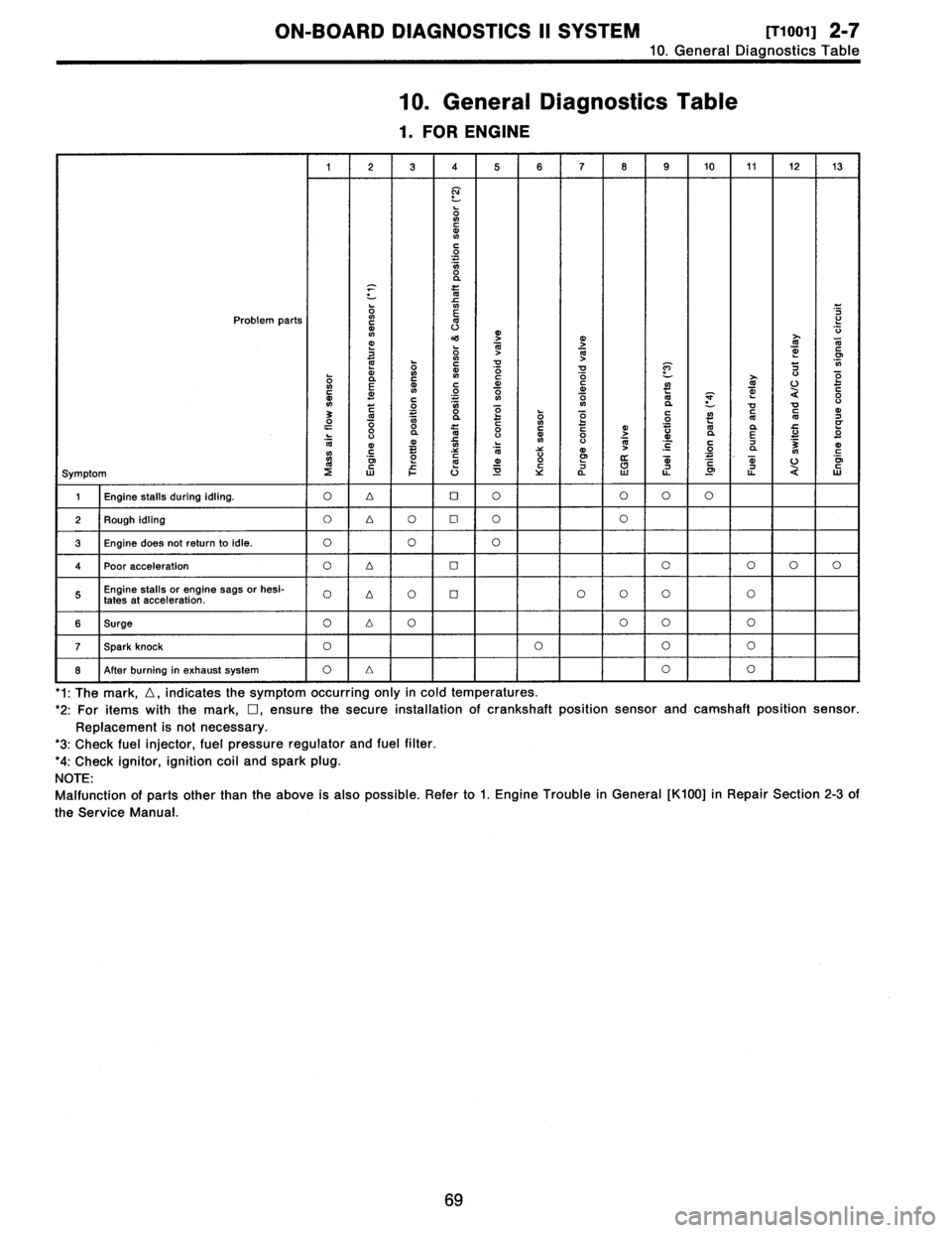
10
.
General
Diagnostics
Table
10
.
General
Diagnostics
Table
1
.
FOR
ENGINE
1
23
4
5678
9
10
11
1213
N
ONCdN
C
O
O
a
x
m
Problem
parts
`o
m
v
mj
4'S
O
1>j
T
N
dm
G
~
ON
41
m
~
!d
V
P]
7
0
E
m
~n
N
~o
C
o
O
d
~
~
U
O
c
m~
C
.
.
.
V1
ON
aVa
U
3
C~
0
"
y
dO1OyOQ
~
"O
CN
d7
O
"
0va
l0
0CdyGo
>
"
Vd
da
E
U
"
O
l0
ymC
~
O
NC
N
V
V
4)
N
~
'C
C
.2
7
a
3NmC
oi
mm
o
W
m
.
mU
o~
Symptom
2WFU~Ya
LL
.0
ti
QW
1
Engine
stalls
during
idling
.
O4OOOOO
2
Rough
idling
O
4O
Cl
OO
3
Engine
does
notreturnto
idle
.
O
OO
4Poor
acceleration
O4OOOOO
Engine
stalls
or
engine
sags
or
hesi-
O
D
OOOOOO
fates
at
acceleration
.
6
Surge
O4OOOO
T
Spark
knock
OOOO
8
After
burning
in
exhaust
system
O
Lr
I
O
I
'1
:
The
mark,
D,
indicates
the
symptom
occurring
only
in
cold
temperatures
.
'2
:
For
itemswiththe
mark,
D,ensure
the
secure
installationof
crankshaft
position
sensor
and
camshaft
position
sensor
.
Replacement
is
not
necessary
.
'3
:
Check
fuel
injector,
fuel
pressure
regulator
and
fuel
filter
.
'4
:
Check
ignitor,
ignition
coil
and
spark
plug
.
NOTE
:
Malfunction
of
partsother
than
the
above
is
also
possible
.
Refer
to
1
.
Engine
Trouble
in
General
[K100]
in
Repair
Section
2-3
of
the
Service
Manual
69
Page 184 of 2890
s-3
[D6013]
6
.
Wiring
Diagram
WIRING
DIAGRAM
Engine
Shield
Boost
Throttle
coolant
point
sensor
position
Knock
temperature
E
.G.R
.
connector
sensor
sensor
sensor
solenoid
B83
H
I
B2
~~
E13
PI
E14
m
I
E8
~I
ElB
..
E2
B21
Ref
.
toAT(
;;
control
system
.
Enginecontro
I
884
module
.
.
..
822
m
mv
E3
m~~;
(Ca
I
i
forn
t
a
mode
l
)
W-
M--
(
9
)
F-F-M-
(
:
9D
Mess
air
Ignitor
flowsensor
(Brown)
E18
E8
(Brown)(Black)
B2
El3
(Brown)
12
123
B3
(Grey)
Bl3
(Gray)
12345123456
Ell
mm
EE
GE
Ignition
coil
E!2
(Gray)
123
82l
(L
i
ght
gray)
1234
5678
9101112
B83
1234
B22
(L
i
ght
gray)
6278
S
1
34
9
101112
3141516
1a
BUR10-02C
14
Page 272 of 2890
6-3
[D6013]
WIRING
DIAGRAM
6
.
Wiring
Diagram
Shield
joint
connector
rE
~
;EB
(
883
E2
B21
Ref
.
toAT
control
system
.
Pressuresensor
....
Englnecontro
I
gg4
module
....
B22
E3
(California
model)
B3
~+~M
B13
Mass
air
Ignitor
flowsensor
(Brown)
E18
E8
(Brown)
(B
I
ack)
B2
E13
(Brown)
12
123
B3
(Grey)
Bl3
(Gray)
12345123456
Ell
(Gray)
123
B21
(L
i
ght
gray)
1234
5678
9
10
ll
l2
Ell
Ignition
coil
883
1234
B22
(L
i
ght
gray)
1
234
S678
9
101112
1
41516
3
fili
BURIO-03C
Eng
i
ne
Throttle
coolant
position
Knock
temperature
E
.
G
.
R
.
sensor
sensor
sensor
solenoid
1
:1
I---I
[--J
[--J
Page 309 of 2890
G2M0093
4) Connect oil pressure gauge hose to cylinder block.
5) Start the engine, and measure oil pressure.
Oil pressure:
98 kPa (1.0 kg/cm
2,14 psi) or more at 800 rpm
294 kPa (3.0 kg/cm2, 43 psi) or more at 5,000 rpm
CAUTION:
�If oil pressure is out of specification, check oil
pump, oil filter and lubrication line.
�If oil pressure warning light is turned ON and oil
pressure is in specification, replace oil pressure
switch.
NOTE:
The specified data is based on an engine oil temperature
of 80°C (176°F).
6) After measuring oil pressure, install oil pressure switch.
Tightening torque:
25±3 N⋅m (2.5±0.3 kg-m, 18.1±2.2 ft-lb)
7) Install generator and V-belt in the reverse order of
removal, and adjust the V-belt deflection.
8
2-2
6. Engine Oil Pressure
Page 503 of 2890

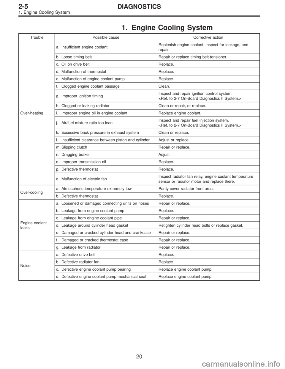
1. Engine Cooling System
Trouble Possible cause Corrective action
Over-heatinga. Insufficient engine coolantReplenish engine coolant, inspect for leakage, and
repair.
b. Loose timing belt Repair or replace timing belt tensioner.
c. Oil on drive belt Replace.
d. Malfunction of thermostat Replace.
e. Malfunction of engine coolant pump Replace.
f. Clogged engine coolant passage Clean.
g. Improper ignition timingInspect and repair ignition control system.
h. Clogged or leaking radiator Clean or repair, or replace.
i. Improper engine oil in engine coolant Replace engine coolant.
j. Air/fuel mixture ratio too leanInspect and repair fuel injection system.
k. Excessive back pressure in exhaust system Clean or replace.
l. Insufficient clearance between piston and cylinder Adjust or replace.
m. Slipping clutch Repair or replace.
n. Dragging brake Adjust.
o. Improper transmission oil Replace.
p. Defective thermostat Replace.
q. Malfunction of electric fanInspect radiator fan relay, engine coolant temperature
sensor or radiator motor and replace there.
Over-coolinga. Atmospheric temperature extremely low Partly cover radiator front area.
b. Defective thermostat Replace.
Engine coolant
leaks.a. Loosened or damaged connecting units on hoses Repair or replace.
b. Leakage from engine coolant pump Replace.
c. Leakage from engine coolant pipe Repair or replace.
d. Leakage around cylinder head gasket Retighten cylinder head bolts or replace gasket.
e. Damaged or cracked cylinder head and crankcase Repair or replace.
f. Damaged or cracked thermostat case Repair or replace.
g. Leakage from radiator Repair or replace.
Noisea. Defective drive belt Replace.
b. Defective radiator fan Replace.
c. Defective engine coolant pump bearing Replace engine coolant pump.
d. Defective engine coolant pump mechanical seal Replace engine coolant pump.
20
2-5DIAGNOSTICS
1. Engine Cooling System