Page 13 of 2890
SERVICE
PROCEDURE
[w3A11
5-5b
3
.
Airbag
Module
3
.
Airbag
Module
A
:
REMOVAL
1
.
DRIVER
SIDE
1)
Set
front
wheels
in
straight
ahead
position
.
2)
Turn
ignition
switch
off
.
3)
Disconnect
ground
cable
from
battery
and
wait
forat
least
20
seconds
before
starting
work
.
4)
Using
TORX9
BIT
T30,
remove
two
TORXO
bolts
.
5)
Disconnect
airbag
connector
on
back
of
airbag
mod-
ule
.
<
Ref
.
to
5-5[M2-6].*1
>
6)
Refer
to
"CAUTION"
for
handling
of
a
removed
airbag
module
.
<
Ref
.
to
5-5
[W300]
.*1
>
3
Page 15 of 2890
SERVICE
PROCEDURE
[W7AO]
5-5b
7
.
Combination
Switch
7
.
Combination
Switch
)
0)0
C
J
~
AB
,
.,
.
-^o/
G5M0312
A
:
REMOVAL
1)
Turn
ignition
switch
off
.
2)
Disconnect
ground
cable
from
battery
and
wait
for
at
least
20
seconds
before
starting
work
.
3)
Remove
lower
cover
.
<
Ref,
to
5-4
[W1A0)
.*1
>
Dis-
connect
airbag
connector
(AB3)
and
(AB8)
below
steering
column
.
CAUTION
:
Do
not
reconnect
airbag
connector
at
steering
column
until
combination
switch
is
securely
re-installed
.
4)
Disconnect
combination
switch
connectors
from
body
harness
connector
.
5)
Set
front
wheels
in
straight
ahead
position
.
Using
TORX9
BIT
T30,
remove
two
TORX9
bolts
.
6)
Disconnect
airbag
connector
on
back
of
airbag
mod-
ule
.
<
Ref
.
to
5-5[M2-6]
.*1
>
Remove
airbag
module,
and
place
it
with
pad
side
facing
upward
.
<
Ref
.
to
5-5
[W300]
.*1
>
7)
Using
steering
puller,
remove
steering
wheel
.
CAUTION
:
Do
not
allow
connector
to
interfere
when
removing
steering
wheel
.
5
Page 319 of 2890

G2M0106
1. General Precautions
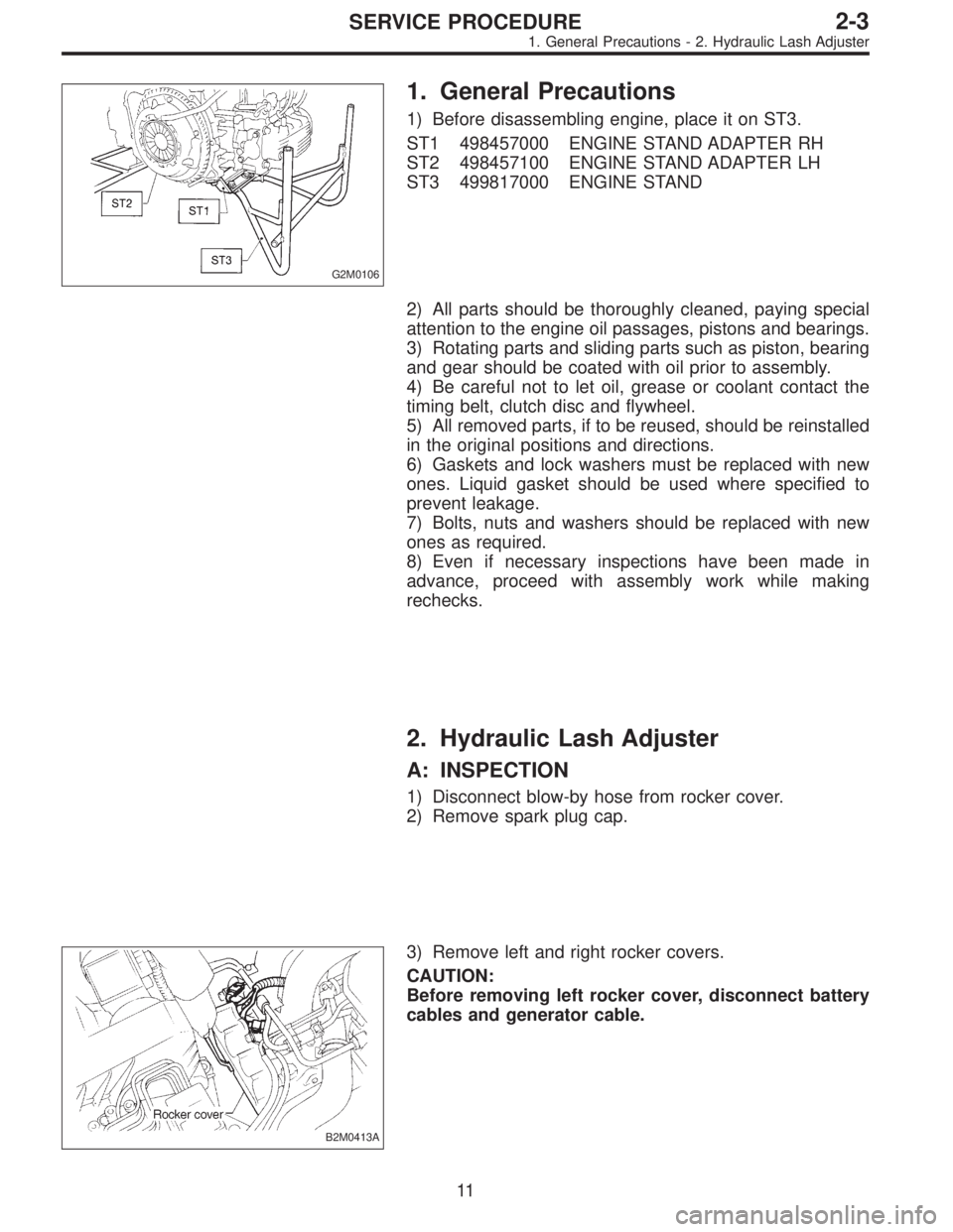
1) Before disassembling engine, place it on ST3.
ST1 498457000 ENGINE STAND ADAPTER RH
ST2 498457100 ENGINE STAND ADAPTER LH
ST3 499817000 ENGINE STAND
2) All parts should be thoroughly cleaned, paying special
attention to the engine oil passages, pistons and bearings.
3) Rotating parts and sliding parts such as piston, bearing
and gear should be coated with oil prior to assembly.
4) Be careful not to let oil, grease or coolant contact the
timing belt, clutch disc and flywheel.
5) All removed parts, if to be reused, should be reinstalled
in the original positions and directions.
6) Gaskets and lock washers must be replaced with new
ones. Liquid gasket should be used where specified to
prevent leakage.
7) Bolts, nuts and washers should be replaced with new
ones as required.
8) Even if necessary inspections have been made in
advance, proceed with assembly work while making
rechecks.
2. Hydraulic Lash Adjuster
A: INSPECTION
1) Disconnect blow-by hose from rocker cover.
2) Remove spark plug cap.
B2M0413A
3) Remove left and right rocker covers.
CAUTION:
Before removing left rocker cover, disconnect battery
cables and generator cable.
11
2-3SERVICE PROCEDURE
1. General Precautions - 2. Hydraulic Lash Adjuster
Page 320 of 2890

G2M0106
1. General Precautions
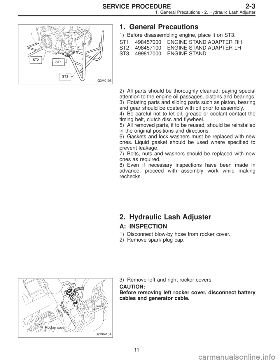
1) Before disassembling engine, place it on ST3.
ST1 498457000 ENGINE STAND ADAPTER RH
ST2 498457100 ENGINE STAND ADAPTER LH
ST3 499817000 ENGINE STAND
2) All parts should be thoroughly cleaned, paying special
attention to the engine oil passages, pistons and bearings.
3) Rotating parts and sliding parts such as piston, bearing
and gear should be coated with oil prior to assembly.
4) Be careful not to let oil, grease or coolant contact the
timing belt, clutch disc and flywheel.
5) All removed parts, if to be reused, should be reinstalled
in the original positions and directions.
6) Gaskets and lock washers must be replaced with new
ones. Liquid gasket should be used where specified to
prevent leakage.
7) Bolts, nuts and washers should be replaced with new
ones as required.
8) Even if necessary inspections have been made in
advance, proceed with assembly work while making
rechecks.
2. Hydraulic Lash Adjuster
A: INSPECTION
1) Disconnect blow-by hose from rocker cover.
2) Remove spark plug cap.
B2M0413A
3) Remove left and right rocker covers.
CAUTION:
Before removing left rocker cover, disconnect battery
cables and generator cable.
11
2-3SERVICE PROCEDURE
1. General Precautions - 2. Hydraulic Lash Adjuster
Page 388 of 2890

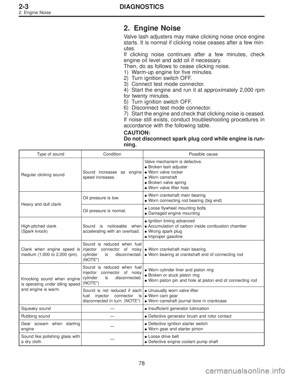
2. Engine Noise
Valve lash adjusters may make clicking noise once engine
starts. It is normal if clicking noise ceases after a few min-
utes.
If clicking noise continues after a few minutes, check
engine oil level and add oil if necessary.
Then, do as follows to cease clicking noise.
1) Warm-up engine for five minutes.
2) Turn ignition switch OFF.
3) Connect test mode connector.
4) Start the engine and run it at approximately 2,000 rpm
for twenty minutes.
5) Turn ignition switch OFF.
6) Disconnect test mode connector.
7) Start the engine and check that clicking noise is ceased.
If noise still exists, conduct troubleshooting procedures in
accordance with the following table.
CAUTION:
Do not disconnect spark plug cord while engine is run-
ning.
Type of sound Condition Possible cause
Regular clicking soundSound increases as engine
speed increases.Valve mechanism is defective.
�Broken lash adjuster
�Worn valve rocker
�Worn camshaft
�Broken valve spring
�Worn valve lifter hole
Heavy and dull clankOil pressure is low.�Worn crankshaft main bearing
�Worn connecting rod bearing (big end)
Oil pressure is normal.�Loose flywheel mounting bolts
�Damaged engine mounting
High-pitched clank
(Spark knock)Sound is noticeable when
accelerating with an overload.�Ignition timing advanced
�Accumulation of carbon inside combustion chamber
�Wrong spark plug
�Improper gasoline
Clank when engine speed is
medium (1,000 to 2,000 rpm).Sound is reduced when fuel
injector connector of noisy
cylinder is disconnected.
(NOTE*)�Worn crankshaft main bearing
�Worn bearing at crankshaft end of connecting rod
Knocking sound when engine
is operating under idling speed
and engine is warm.Sound is reduced when fuel
injector connector of noisy
cylinder is disconnected.
(NOTE*)�Worn cylinder liner and piston ring
�Broken or stuck piston ring
�Worn piston pin and hole at piston end of connecting rod
Sound is not reduced if each
fuel injector connector is
disconnected in turn. (NOTE*)�Unusually worn valve lifter
�Worn cam gear
�Worn camshaft journal bore in crankcase
Squeaky sound—�Insufficient generator lubrication
Rubbing sound—�Defective generator brush and rotor contact
Gear scream when starting
engine—�Defective ignition starter switch
�Worn gear and starter pinion
Sound like polishing glass with
a dry cloth—�Loose drive belt
�Defective engine coolant pump shaft
78
2-3DIAGNOSTICS
2. Engine Noise
Page 399 of 2890
G2M0709
1. General Precautions
1) Before disassembling engine, place it on ST3.
ST1 498457000 ENGINE STAND ADAPTER RH
ST2 498457100 ENGINE STAND ADAPTER LH
ST3 499817000 ENGINE STAND
2) All parts should be thoroughly cleaned, paying special
attention to the engine oil passages, pistons and bearings.
3) Rotating parts and sliding parts such as piston, bearing
and gear should be coated with oil prior to assembly.
4) Be careful not to let oil, grease or coolant contact the
timing belt, clutch disc and flywheel.
5) All removed parts, if to be reused, should be reinstalled
in the original positions and directions.
6) Gaskets and lock washers must be replaced with new
ones. Liquid gasket should be used where specified to
prevent leakage.
7) Bolts, nuts and washers should be replaced with new
ones as required.
8) Even if necessary inspections have been made in
advance, proceed with assembly work while making
rechecks.
11
2-3bSERVICE PROCEDURE
1. General Precautions
Page 467 of 2890

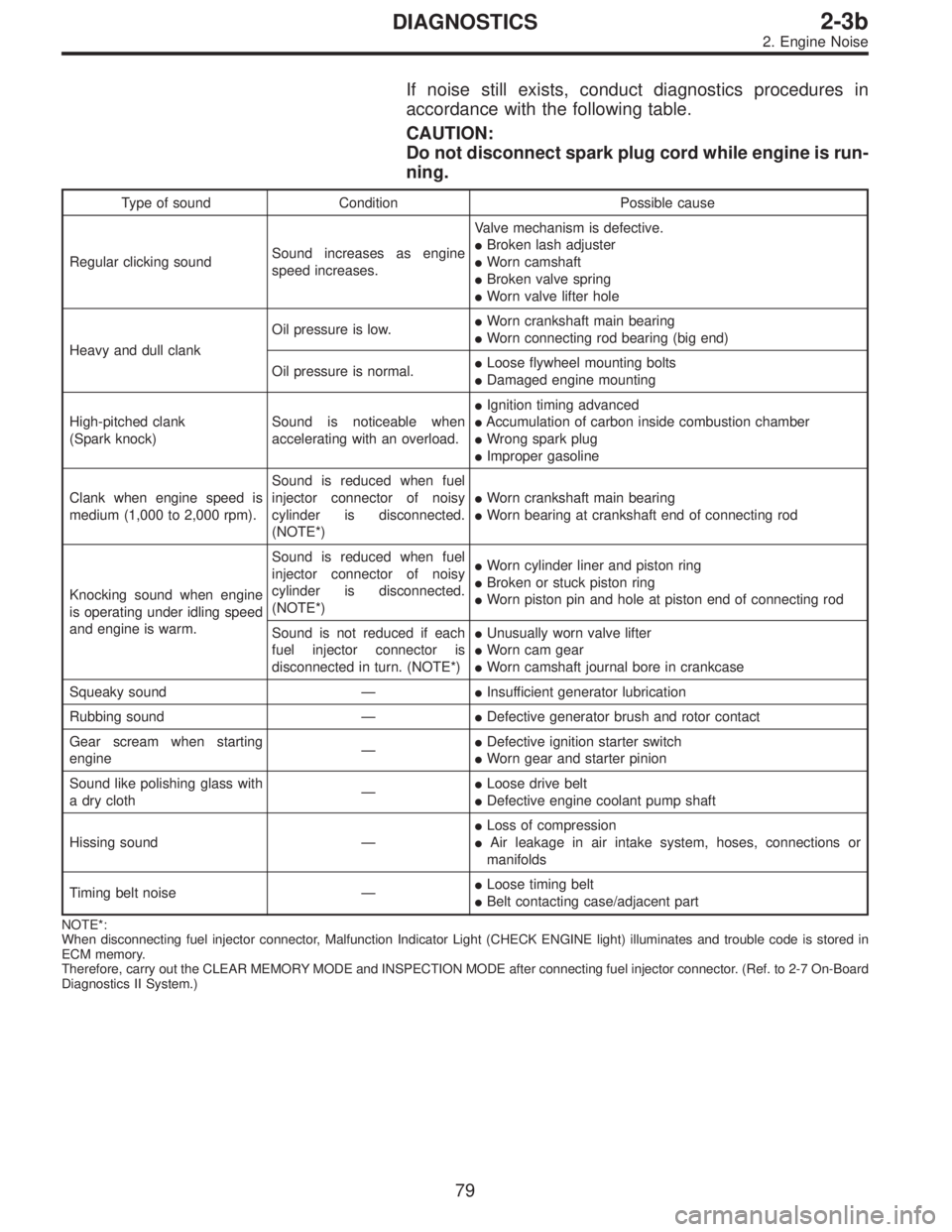
If noise still exists, conduct diagnostics procedures in
accordance with the following table.
CAUTION:
Do not disconnect spark plug cord while engine is run-
ning.
Type of sound Condition Possible cause
Regular clicking soundSound increases as engine
speed increases.Valve mechanism is defective.
�Broken lash adjuster
�Worn camshaft
�Broken valve spring
�Worn valve lifter hole
Heavy and dull clankOil pressure is low.�Worn crankshaft main bearing
�Worn connecting rod bearing (big end)
Oil pressure is normal.�Loose flywheel mounting bolts
�Damaged engine mounting
High-pitched clank
(Spark knock)Sound is noticeable when
accelerating with an overload.�Ignition timing advanced
�Accumulation of carbon inside combustion chamber
�Wrong spark plug
�Improper gasoline
Clank when engine speed is
medium (1,000 to 2,000 rpm).Sound is reduced when fuel
injector connector of noisy
cylinder is disconnected.
(NOTE*)�Worn crankshaft main bearing
�Worn bearing at crankshaft end of connecting rod
Knocking sound when engine
is operating under idling speed
and engine is warm.Sound is reduced when fuel
injector connector of noisy
cylinder is disconnected.
(NOTE*)�Worn cylinder liner and piston ring
�Broken or stuck piston ring
�Worn piston pin and hole at piston end of connecting rod
Sound is not reduced if each
fuel injector connector is
disconnected in turn. (NOTE*)�Unusually worn valve lifter
�Worn cam gear
�Worn camshaft journal bore in crankcase
Squeaky sound—�Insufficient generator lubrication
Rubbing sound—�Defective generator brush and rotor contact
Gear scream when starting
engine—�Defective ignition starter switch
�Worn gear and starter pinion
Sound like polishing glass with
a dry cloth—�Loose drive belt
�Defective engine coolant pump shaft
Hissing sound—�Loss of compression
�Air leakage in air intake system, hoses, connections or
manifolds
Timing belt noise—�Loose timing belt
�Belt contacting case/adjacent part
NOTE*:
When disconnecting fuel injector connector, Malfunction Indicator Light (CHECK ENGINE light) illuminates and trouble code is stored in
ECM memory.
Therefore, carry out the CLEAR MEMORY MODE and INSPECTION MODE after connecting fuel injector connector. (Ref. to 2-7 On-Board
Diagnostics II System.)
79
2-3bDIAGNOSTICS
2. Engine Noise
Page 527 of 2890
B2M0334
(3) Remove bolts which install power steering pump
from bracket.
B2M0029
(4) Place power steering pump on the right side wheel
apron.
B6M0160
8) Disconnect spark plug cords from ignition coil.
H2M1246
9) Disconnect engine coolant hoses from throttle body.
H2M1259A
10) Disconnect engine coolant hose�1from idle air con-
trol solenoid valve.
11) Disconnect air by-pass hose�
2from idle air control
solenoid valve.
9
2-7SERVICE PROCEDURE
4. Intake Manifold