Page 1120 of 2890
 Insert combination switch to upper column shaft, and
install lower column cover with tilt lever held in the lowered
position. Then route ignition key harness and combination
swi")
B4M0555
D: ASSEMBLY
1) Insert combination switch to upper column shaft, and
install lower column cover with tilt lever held in the lowered
position. Then route ignition key harness and combination
switch harness between column cover mounting bosses.
2) Fit upper column cover to lower column cover, and
tighten combination switch and column cover.
Tightening torque:
1.2±0.2 N⋅m (0.12±0.02 kg-m, 0.9±0.1 ft-lb)
CAUTION:
Don’t overtorque screw.
E: INSTALLATION
1) Insert end of steering shaft into toe board grommet.
2) Tighten steering shaft mounting bolts under instrument
panel.
Tightening torque:
25±5 N⋅m (2.5±0.5 kg-m, 18.1±3.6 ft-lb)
3) Connect ignition and combination switch connectors
under instrument panel.
4) Connect airbag system connector at harness spool.
NOTE:
Make sure to apply double lock.
5) Install universal joint.
(1) Align bolt hole on the long yoke side of universal
joint with the cutout at the serrated section of shaft end,
and insert universal joint.
(2) Align bolt hole on the short yoke side of universal
joint with the cutout at the serrated section of gearbox
assembly. Lower universal joint completely.
(3) Temporarily tighten bolt on the short yoke side.
Raise universal joint to make sure the bolt is properly
passing through the cutout at the serrated section.
(4) Tighten bolt on the long yoke side, then that on the
short yoke side.
Tightening torque:
24±3 N⋅m (2.4±0.3 kg-m, 17.4±2.2 ft-lb)
CAUTION:
�Make sure that universal joint bolts is tightened
through notch in shaft serration.
�Excessively large tightening torque of universal
joint bolts may lead to heavy steering wheel operation.
Standard clearance between gearbox to DOJ:
Over 15 mm (0.59 in)
13
4-3SERVICE PROCEDURE
2. Tilt Steering Column
Page 1137 of 2890
 Disconnect battery negative terminal.
2) Disconnect both oxygen sensor and exhaust gas tem-
perature warning sensor connectors from front exhaust
pipe assembly.
WARNING:
Be careful as ex")
A: REMOVAL
1) Disconnect battery negative terminal.
2) Disconnect both oxygen sensor and exhaust gas tem-
perature warning sensor connectors from front exhaust
pipe assembly.
WARNING:
Be careful as exhaust pipe is hot.
3) Raise vehicle with a jack and remove front wheel.
4) Disconnect front exhaust pipe assembly.
G4M0097
5) Remove cotter pin and castle nut. Using a puller,
remove tie-rod end from knuckle arm.
G4M0098
6) Remove jack-up plate and stabilizer.
G4M0786
7) Disconnect one pipe joint A from center of gearbox
assembly, and connect a vinyl hose to it. While turning
steering wheel to the left and right, drain fluid through the
hose. Similarly, drain fluid from the other pipe joint B.
G4M0787
8) Remove lower and upper bolts from universal joint, and
remove universal joint in the upward direction.
NOTE:
Scribe alignment marks on universal joint so that it can be
reassembled at the original serration.
30
4-3SERVICE PROCEDURE
4. Steering Gearbox (Power Steering System) [RHD model]
Page 1245 of 2890
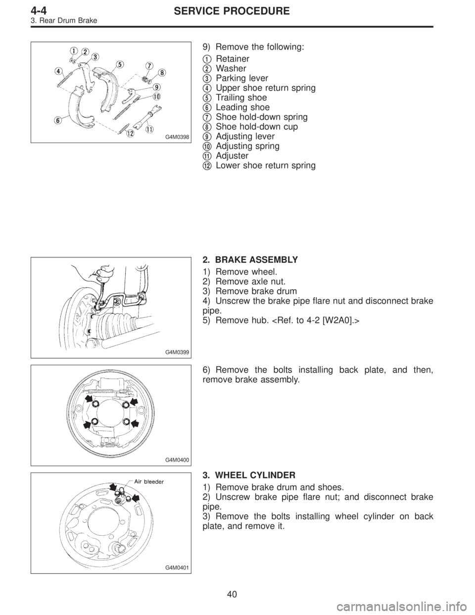
G4M0398
9) Remove the following:
�
1Retainer
�
2Washer
�
3Parking lever
�
4Upper shoe return spring
�
5Trailing shoe
�
6Leading shoe
�
7Shoe hold-down spring
�
8Shoe hold-down cup
�
9Adjusting lever
�
10Adjusting spring
�
11Adjuster
�
12Lower shoe return spring
G4M0399
2. BRAKE ASSEMBLY
1) Remove wheel.
2) Remove axle nut.
3) Remove brake drum
4) Unscrew the brake pipe flare nut and disconnect brake
pipe.
5) Remove hub.
G4M0400
6) Remove the bolts installing back plate, and then,
remove brake assembly.
G4M0401
3. WHEEL CYLINDER
1) Remove brake drum and shoes.
2) Unscrew brake pipe flare nut; and disconnect brake
pipe.
3) Remove the bolts installing wheel cylinder on back
plate, and remove it.
40
4-4SERVICE PROCEDURE
3. Rear Drum Brake
Page 1247 of 2890
 Assembly i")
D: ASSEMBLY
1. WHEEL CYLINDER
Clean all parts in brake fluid. Check and replace faulty
parts.
�Cup and boot for damage or fatigue
�Cylinder, piston and spring or damage or rust formation
1) Assembly is the reverse order of disassembly.
G4M0404
(1) When installing the cup, use ST, apply brake fluid
to the frictional surface for smooth installation and pay
attention to cup direction.
(2) STs are available in different sizes.
CAUTION:
�When replacing the repair kit, make sure that the
sizes of cylinder and cup are the same as those which
were replaced.
�Use only the tool of the correct size.
ST: ADAPTER
Applicable size Part No.
17.46 mm (11/16 in) 925460000
19.05 mm (3/4 in) 926460000
CAUTION:
While assembling, be careful to prevent any metal
chip, dust or dirt from entering the wheel cylinder.
G4M0405
2) Apply rubber grease to the boot inside as shown in
Figure.
Grease:
NIGLUBE RX-2 (Part No. 003606000)
CAUTION:
Never use brake grease.
G4M0401
E: INSTALLATION
1. WHEEL CYLINDER
Install wheel cylinder on back plate, and tighten bolts.
Tightening torque:
10±2 N⋅m (1.0±0.2 kg-m, 7.2±1.4 ft-lb)
42
4-4SERVICE PROCEDURE
3. Rear Drum Brake
Page 1248 of 2890
 Clean back plate and wheel cylinder.
2) Apply grease to portions indicated by arrows in Figure.
Brake grease:
Dow Corning Molykote No. 7439 (Part No.
725191460)
G4M04")
G4M0407
2. BRAKE DRUM AND SHOE
1) Clean back plate and wheel cylinder.
2) Apply grease to portions indicated by arrows in Figure.
Brake grease:
Dow Corning Molykote No. 7439 (Part No.
725191460)
G4M0408
3) Apply grease to adjusting screw and both ends of
adjuster.
Brake grease:
Dow Corning Molykote No. 7439 (Part No.
725191460)
4) Connect upper shoe return spring to shoes.
G4M0409
5) While positioning shoes (one at a time) in groove on
wheel cylinder, secure shoes.
6) Connect lower shoe return spring.
7) Fix shoes by connecting hold-down cup to hold-down
pin.
G4M0400
3. BRAKE ASSEMBLY
1) Install brake assembly on housing, and tighten bolts to
install back plate.
Tightening torque:
52±6 N⋅m (5.3±0.6 kg-m, 38.3±4.3 ft-lb)
2) Install hub.
3) Connect brake pipe, and tighten brake pipe flange nut.
Tightening torque:
15
+3
�2N⋅m (1.5+0.3
�0.2kg-m, 10.8+2.2
�1.4ft-lb)
4) Set the outside diameter of brake shoes less than 0.5
to 0.8 mm (0.020 to 0.031 in) in comparison with the inside
diameter of brake drum.
5) Install brake drum.
6) After installing brake assembly, bleed air from brake
line.
43
4-4SERVICE PROCEDURE
3. Rear Drum Brake
Page 1335 of 2890
 Fluid leakage from the hydraulic mechanismRepair or replace (cup, piston seal, piston boot, master cylin")
1. Entire Brake System
Trouble and possible cause Corrective action
1. Insufficient braking
(1) Fluid leakage from the hydraulic mechanismRepair or replace (cup, piston seal, piston boot, master cylinder
piston kit, pipe or hose).
(2) Entry of air into the hydraulic mechanism Bleed the air.
(3) Excessively wide shoe clearance Adjust the clearance.
(4) Wear, deteriorated surface material, adhering water or fluid
on the liningReplace, grind or clean.
(5) Improper operation of master cylinder, disc caliper, brake
booster or check valveCorrect or replace.
2. Unstable or uneven braking
(1) Fluid on the lining, drum or rotor Eliminate cause of fluid leakage, clean, or replace.
(2) Drum or rotor eccentricity Correct or replace the drum or rotor.
(3) Worn brake drum, or damage to the drum caused by sand Correct by grinding, or replace.
(4) Improper lining contact, deteriorated surface material,
improper inferior material, or wearCorrect by grinding, or replace.
(5) Deformed back plate Correct or replace.
(6) Improper tire inflation Inflate to correct pressure.
(7) Disordered wheel alignment Adjust alignment.
(8) Loosened back plate or the support installing bolts Retighten.
(9) Loosened wheel bearing Retighten to normal tightening torque or replace.
(10) Trouble in the hydraulic system Replace the cylinder, brake pipe or hose.
(11) Uneven effect of the parking brake Check, adjust, or replace the rear brake and cable system.
3. Excessive pedal stroke
(1) Entry of air into the hydraulic mechanism Bleed the air.
(2) Excessive play in the master cylinder push rod Adjust.
(3) Fluid leakage from the hydraulic mechanismRepair or replace (cup, piston seal, piston boot, master cylinder
piston kit, pipe or hose).
(4) Improperly adjusted shoe clearance Adjust.
(5) Improper lining contact or worn lining Correct or replace.
124
4-4DIAGNOSTICS
1. Entire Brake System
Page 1336 of 2890
 Insufficient pedal play Adjust play.
(2) Improper master cylinder return Clean or replace the cylinder.
(3)")
Trouble and possible cause Corrective action
4. Brake dragging or improper brake return
(1) Insufficient pedal play Adjust play.
(2) Improper master cylinder return Clean or replace the cylinder.
(3) Clogged hydraulic system Replace.
(4) Improper return or adjustment of parking brake Correct or adjust.
(5) Weakened spring tension or breakage of shoe return spring Replace the spring.
(6) Excessively narrow shoe clearance Adjust the clearance.
(7) Improper disc caliper operation Correct or replace.
(8) Improper adjusted wheel bearing Adjust or replace.
5. Brake noise (1) (creak sound)
(1) Hardened or deteriorated lining Replace the shoe assembly or pad.
(2) Worn lining Replace the shoe assembly or pad.
(3) Loosened back plate or the support installing bolts Retighten.
(4) Loose wheel bearing Retighten to normal tightening torque.
(5) Dirty drum or rotor Clean the drum or rotor, or clean and replace the brake assembly.
6. Brake noise (2) (hissing sound)
(1) Worn lining Replace the shoe assembly or pad.
(2) Improper installed shoe or pad Correct or replace the shoe assembly or pad.
(3) Loose or bent drum or rotor Retighten or replace.
7. Brake noise (3) (click sound)
In the case of the disc brake:
(1) Excessively worn pad or the support Replace the pad or the support.
In the case of the drum brake:
(1) Excessively worn shoe ridge Replace the back plate.
(2) Lack of oil on the shoe ridge surface and anchor Add more grease.
125
4-4DIAGNOSTICS
1. Entire Brake System
Page 1581 of 2890
A: REMOVAL
1. DRIVER SIDE
1) Set front wheels in straight ahead position.
2) Turn ignition switch off.
3) Disconnect ground cable from battery and wait for at
least 20 seconds before starting work.
H5M0662A
4) Using TORX®BIT T30, remove two TORX®bolts.
H5M0664
5) Disconnect airbag connector on back of airbag module.
6) Refer to“CAUTION”for handling of a removed airbag
module.
2. PASSENGER SIDE
1) Remove instrument panel.
12
5-5SERVICE PROCEDURE
3. Airbag Module
 Set front wheels in straight ahead position.
2) Turn ignition switch off.
3) Disconnect ground cable from battery and wait for at
least 20 seconds before starting work.
H5")