Page 595 of 2890
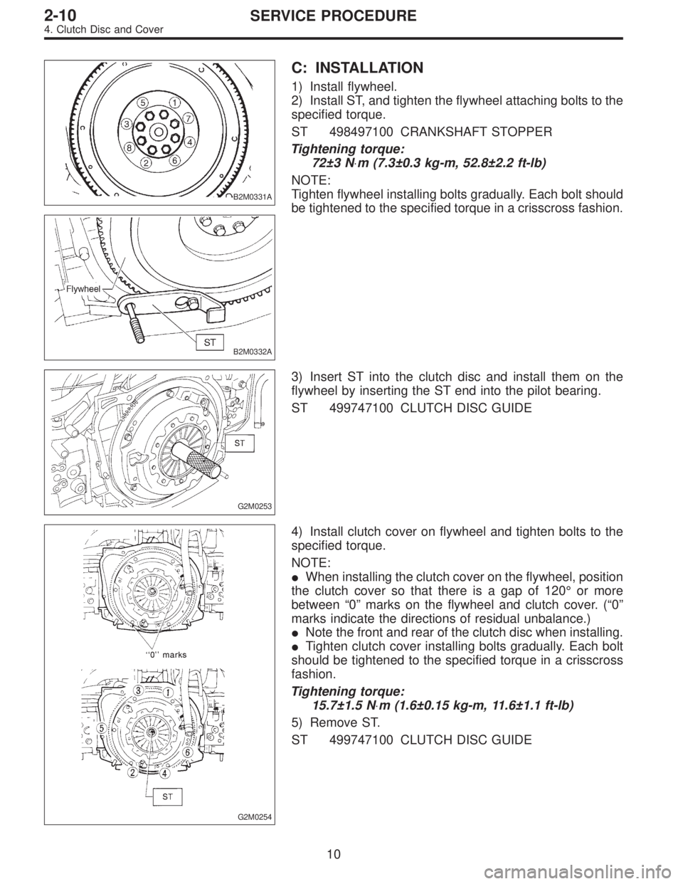
B2M0331A
B2M0332A
C: INSTALLATION
1) Install flywheel.
2) Install ST, and tighten the flywheel attaching bolts to the
specified torque.
ST 498497100 CRANKSHAFT STOPPER
Tightening torque:
72±3 N⋅m (7.3±0.3 kg-m, 52.8±2.2 ft-lb)
NOTE:
Tighten flywheel installing bolts gradually. Each bolt should
be tightened to the specified torque in a crisscross fashion.
G2M0253
3) Insert ST into the clutch disc and install them on the
flywheel by inserting the ST end into the pilot bearing.
ST 499747100 CLUTCH DISC GUIDE
G2M0254
4) Install clutch cover on flywheel and tighten bolts to the
specified torque.
NOTE:
�When installing the clutch cover on the flywheel, position
the clutch cover so that there is a gap of 120°or more
between“0”marks on the flywheel and clutch cover. (“0”
marks indicate the directions of residual unbalance.)
�Note the front and rear of the clutch disc when installing.
�Tighten clutch cover installing bolts gradually. Each bolt
should be tightened to the specified torque in a crisscross
fashion.
Tightening torque:
15.7±1.5 N⋅m (1.6±0.15 kg-m, 11.6±1.1 ft-lb)
5) Remove ST.
ST 499747100 CLUTCH DISC GUIDE
10
2-10SERVICE PROCEDURE
4. Clutch Disc and Cover
Page 629 of 2890
B2M0334
(3) Remove bolts which install power steering pump
from bracket.
B2M0029
(4) Place power steering pump on the right side wheel
apron.
B6M0160
8) Disconnect spark plug cords from ignition coil.
H2M1246
9) Disconnect engine coolant hoses from throttle body.
H2M1259A
10) Disconnect engine coolant hose�1from idle air con-
trol solenoid valve.
11) Disconnect air by-pass hose�
2from idle air control
solenoid valve.
9
2-7SERVICE PROCEDURE
4. Intake Manifold
Page 711 of 2890
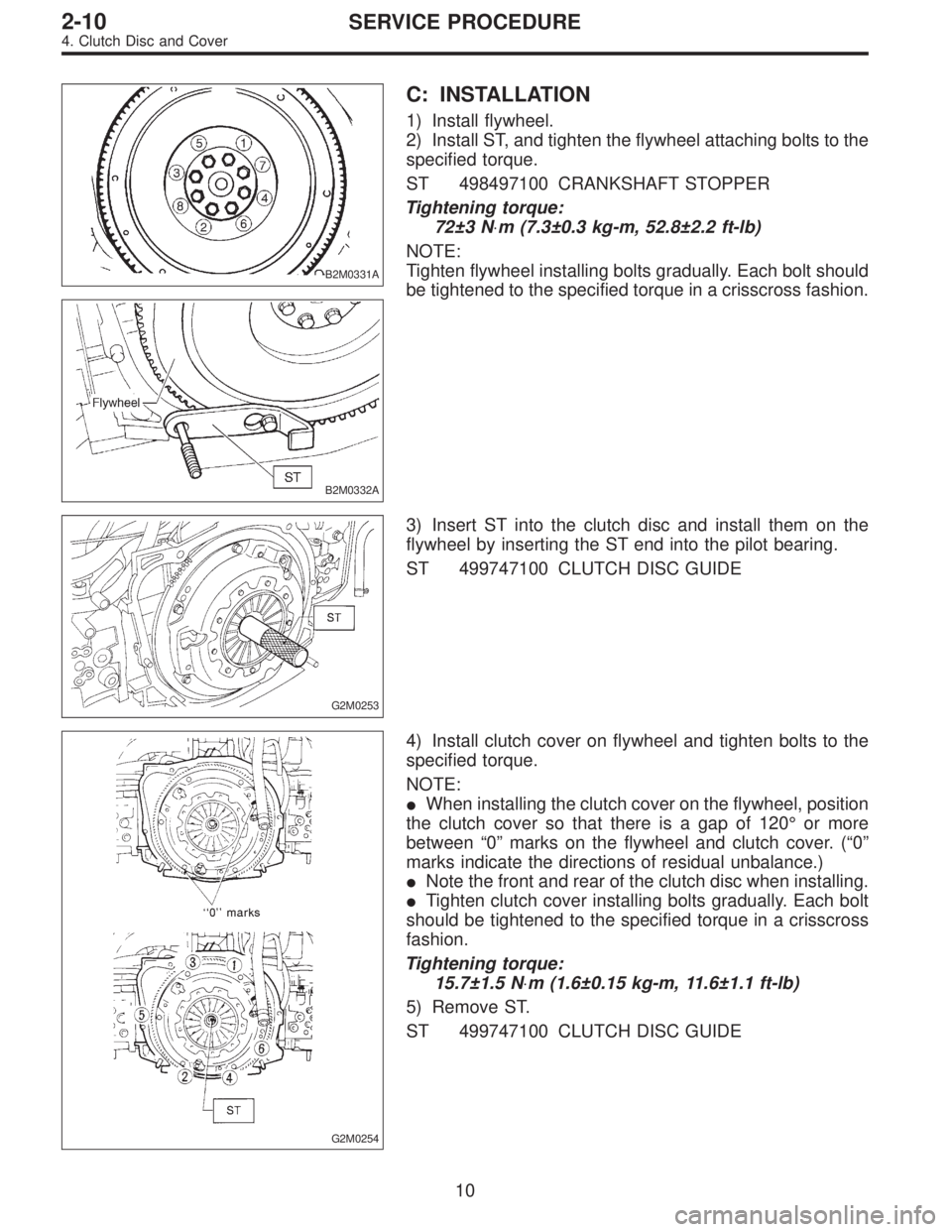
B2M0331A
B2M0332A
C: INSTALLATION
1) Install flywheel.
2) Install ST, and tighten the flywheel attaching bolts to the
specified torque.
ST 498497100 CRANKSHAFT STOPPER
Tightening torque:
72±3 N⋅m (7.3±0.3 kg-m, 52.8±2.2 ft-lb)
NOTE:
Tighten flywheel installing bolts gradually. Each bolt should
be tightened to the specified torque in a crisscross fashion.
G2M0253
3) Insert ST into the clutch disc and install them on the
flywheel by inserting the ST end into the pilot bearing.
ST 499747100 CLUTCH DISC GUIDE
G2M0254
4) Install clutch cover on flywheel and tighten bolts to the
specified torque.
NOTE:
�When installing the clutch cover on the flywheel, position
the clutch cover so that there is a gap of 120°or more
between“0”marks on the flywheel and clutch cover. (“0”
marks indicate the directions of residual unbalance.)
�Note the front and rear of the clutch disc when installing.
�Tighten clutch cover installing bolts gradually. Each bolt
should be tightened to the specified torque in a crisscross
fashion.
Tightening torque:
15.7±1.5 N⋅m (1.6±0.15 kg-m, 11.6±1.1 ft-lb)
5) Remove ST.
ST 499747100 CLUTCH DISC GUIDE
10
2-10SERVICE PROCEDURE
4. Clutch Disc and Cover
Page 729 of 2890
G2M0286
11) Remove power steering pump from bracket.
(1) Loosen lock bolt and slider bolt, and remove front
side V-belt.
B2M0340
(2) Remove pipe with bracket from intake manifold.
B2M0334
(3) Remove bolts which install power steering pump
from bracket.
B2M0029
(4) Place power steering pump on the right side wheel
apron.
G2M0290
12) Remove front exhaust pipe and center exhaust pipe.
(1) Lift-up the vehicle.
(2) Remove nuts which install front exhaust pipe onto
engine.
16
2-11SERVICE PROCEDURE
2. Engine
Page 968 of 2890
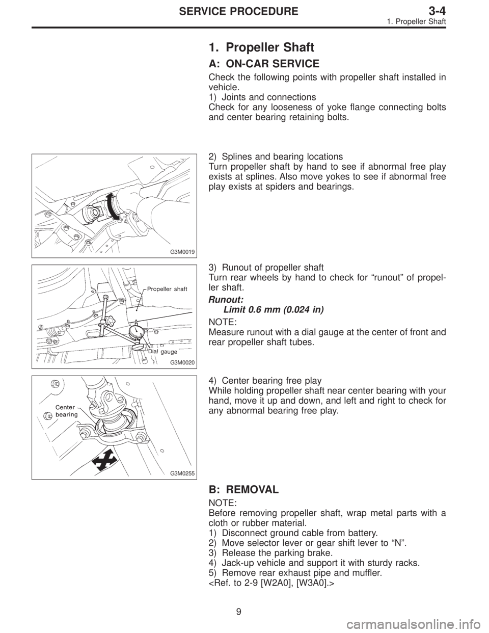
1. Propeller Shaft
A: ON-CAR SERVICE
Check the following points with propeller shaft installed in
vehicle.
1) Joints and connections
Check for any looseness of yoke flange connecting bolts
and center bearing retaining bolts.
G3M0019
2) Splines and bearing locations
Turn propeller shaft by hand to see if abnormal free play
exists at splines. Also move yokes to see if abnormal free
play exists at spiders and bearings.
G3M0020
3) Runout of propeller shaft
Turn rear wheels by hand to check for“runout”of propel-
ler shaft.
Runout:
Limit 0.6 mm (0.024 in)
NOTE:
Measure runout with a dial gauge at the center of front and
rear propeller shaft tubes.
G3M0255
4) Center bearing free play
While holding propeller shaft near center bearing with your
hand, move it up and down, and left and right to check for
any abnormal bearing free play.
B: REMOVAL
NOTE:
Before removing propeller shaft, wrap metal parts with a
cloth or rubber material.
1) Disconnect ground cable from battery.
2) Move selector lever or gear shift lever to“N”.
3) Release the parking brake.
4) Jack-up vehicle and support it with sturdy racks.
5) Remove rear exhaust pipe and muffler.
9
3-4SERVICE PROCEDURE
1. Propeller Shaft
Page 999 of 2890
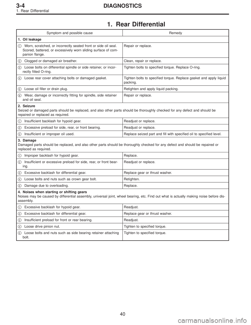
1. Rear Differential
Symptom and possible cause Remedy
1. Oil leakage
�
1Worn, scratched, or incorrectly seated front or side oil seal.
Scored, battered, or excessively worn sliding surface of com-
panion flange.Repair or replace.
�
2Clogged or damaged air breather. Clean, repair or replace.
�
3Loose bolts on differential spindle or side retainer, or incor-
rectly fitted O-ring.Tighten bolts to specified torque. Replace O-ring.
�
4Loose rear cover attaching bolts or damaged gasket. Tighten bolts to specified torque. Replace gasket and apply liquid
packing.
�
5Loose oil filler or drain plug. Retighten and apply liquid packing.
�
6Wear, damage or incorrectly fitting for spindle, side retainer
and oil seal.Repair or replace.
2. Seizure
Seized or damaged parts should be replaced, and also other parts should be thoroughly checked for any defect and should be
repaired or replaced as required.
�
1Insufficient backlash for hypoid gear. Readjust or replace.
�
2Excessive preload for side, rear, or front bearing. Readjust or replace.
�
3Insufficient or improper oil used. Replace seized part and fill with specified oil to specified level.
3. Damage
Damaged parts should be replaced, and also other parts should be thoroughly checked for any defect and should be repaired or
replaced as required.
�
1Improper backlash for hypoid gear. Replace.
�
2Insufficient or excessive preload for side, rear, or front bear-
ing.Readjust or replace.
�
3Excessive backlash for differential gear. Replace gear or thrust washer.
�
4Loose bolts and nuts such as crown gear bolt. Retighten.
�
5Damage due to overloading. Replace.
4. Noises when starting or shifting gears
Noises may be caused by differential assembly, universal joint, wheel bearing, etc. Find out what is actually making noise before dis-
assembly.
�
1Excessive backlash for hypoid gear. Readjust.
�
2Excessive backlash for differential gear. Replace gear or thrust washer.
�
3Insufficient preload for front or rear bearing. Readjust.
�
4Loose drive pinion nut. Tighten to specified torque.
�
5Loose bolts and nuts such as side bearing retainer attaching
bolt.Tighten to specified torque.
40
3-4DIAGNOSTICS
1. Rear Differential
Page 1015 of 2890
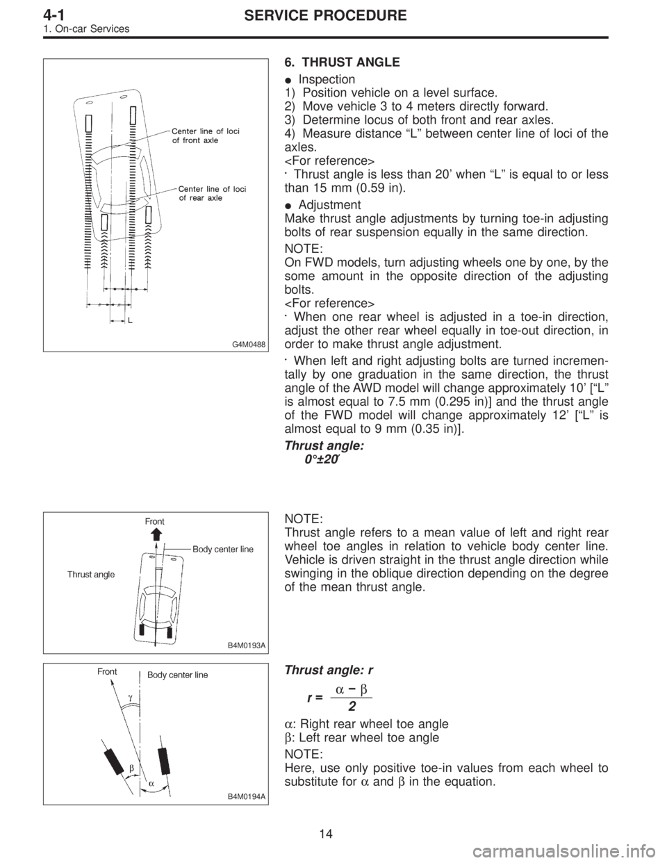
G4M0488
6. THRUST ANGLE
�Inspection
1) Position vehicle on a level surface.
2) Move vehicle 3 to 4 meters directly forward.
3) Determine locus of both front and rear axles.
4) Measure distance“L”between center line of loci of the
axles.
Thrust angle is less than 20’when“L”is equal to or less
than 15 mm (0.59 in).
�Adjustment
Make thrust angle adjustments by turning toe-in adjusting
bolts of rear suspension equally in the same direction.
NOTE:
On FWD models, turn adjusting wheels one by one, by the
some amount in the opposite direction of the adjusting
bolts.
When one rear wheel is adjusted in a toe-in direction,
adjust the other rear wheel equally in toe-out direction, in
order to make thrust angle adjustment.
When left and right adjusting bolts are turned incremen-
tally by one graduation in the same direction, the thrust
angle of the AWD model will change approximately 10’[“L”
is almost equal to 7.5 mm (0.295 in)] and the thrust angle
of the FWD model will change approximately 12’[“L”is
almost equal to 9 mm (0.35 in)].
Thrust angle:
0°±20′
B4M0193A
NOTE:
Thrust angle refers to a mean value of left and right rear
wheel toe angles in relation to vehicle body center line.
Vehicle is driven straight in the thrust angle direction while
swinging in the oblique direction depending on the degree
of the mean thrust angle.
B4M0194A
Thrust angle: r
r=α�β2
α: Right rear wheel toe angle
β: Left rear wheel toe angle
NOTE:
Here, use only positive toe-in values from each wheel to
substitute forαandβin the equation.
14
4-1SERVICE PROCEDURE
1. On-car Services
Page 1020 of 2890
G4M0497
4) Connect stabilizer link to transverse link, and tempo-
rarily tighten bolts.
CAUTION:
Discard loosened self-locking nut and replace with a
new one.
5) Tighten the following points in the order shown below
when wheels are in full contact with the ground and vehicle
is at curb weight condition.
(1) Transverse link and stabilizer link
Tightening torque:
29±5 N⋅m (3.0±0.5 kg-m, 21.7±3.6 ft-lb)
(2) Transverse link and crossmember
Tightening torque:
98±15 N⋅m (10.0±1.5 kg-m, 72±11 ft-lb)
G4M0928
(3) Transverse link rear bushing and body
Tightening torque:
245±49 N⋅m (25±5 kg-m, 181±36 ft-lb)
NOTE:
�Move rear bushing back and forth until transverse link-
to-rear bushing clearance is established (as indicated in
figure.) before tightening.
�Check wheel alignment and adjust if necessary.
19
4-1SERVICE PROCEDURE
2. Front Transverse Link