Page 1060 of 2890
G4M0230
D: ASSEMBLY
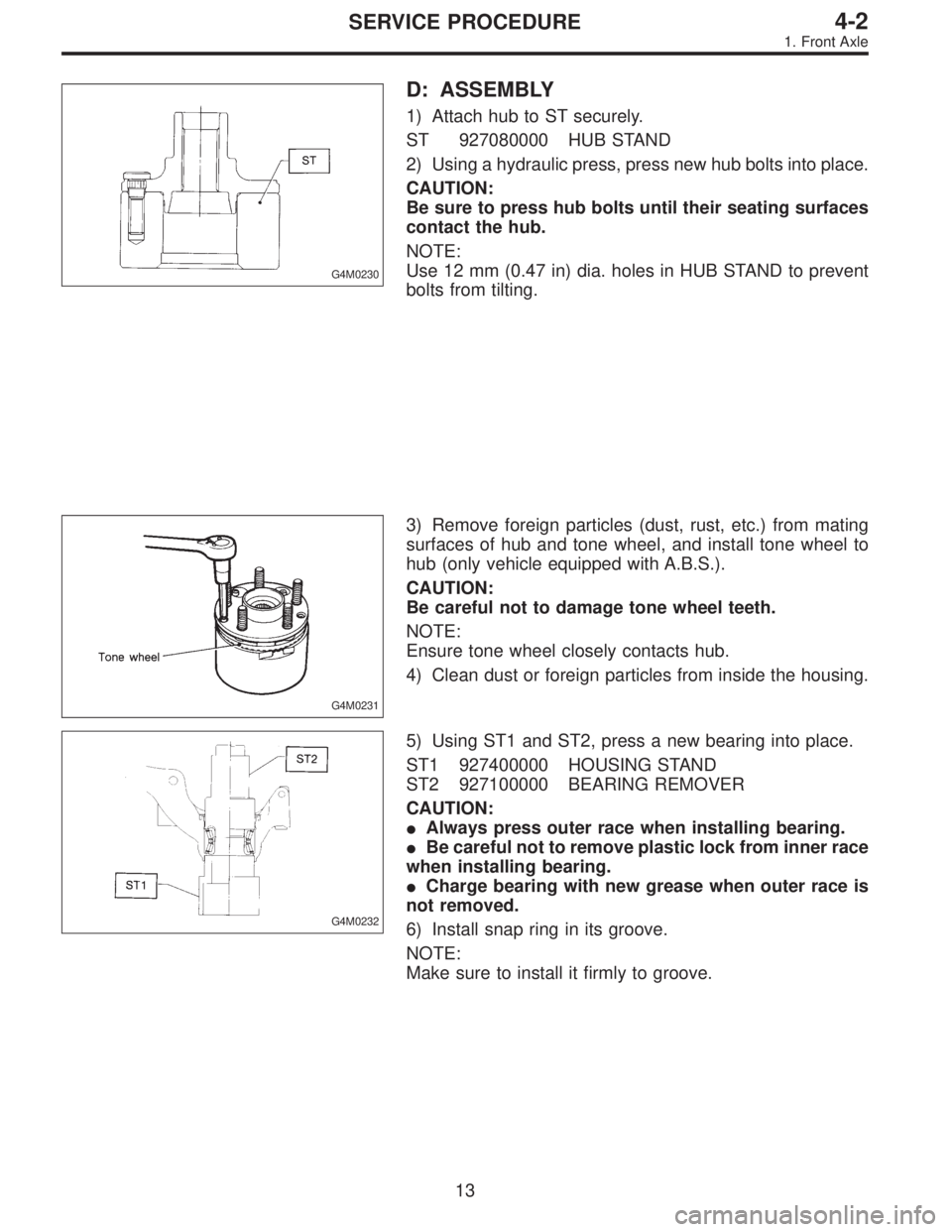
1) Attach hub to ST securely.
ST 927080000 HUB STAND
2) Using a hydraulic press, press new hub bolts into place.
CAUTION:
Be sure to press hub bolts until their seating surfaces
contact the hub.
NOTE:
Use 12 mm (0.47 in) dia. holes in HUB STAND to prevent
bolts from tilting.
G4M0231
3) Remove foreign particles (dust, rust, etc.) from mating
surfaces of hub and tone wheel, and install tone wheel to
hub (only vehicle equipped with A.B.S.).
CAUTION:
Be careful not to damage tone wheel teeth.
NOTE:
Ensure tone wheel closely contacts hub.
4) Clean dust or foreign particles from inside the housing.
G4M0232
5) Using ST1 and ST2, press a new bearing into place.
ST1 927400000 HOUSING STAND
ST2 927100000 BEARING REMOVER
CAUTION:
�Always press outer race when installing bearing.
�Be careful not to remove plastic lock from inner race
when installing bearing.
�Charge bearing with new grease when outer race is
not removed.
6) Install snap ring in its groove.
NOTE:
Make sure to install it firmly to groove.
13
4-2SERVICE PROCEDURE
1. Front Axle
Page 1067 of 2890
G4M0250
B: DISASSEMBLY
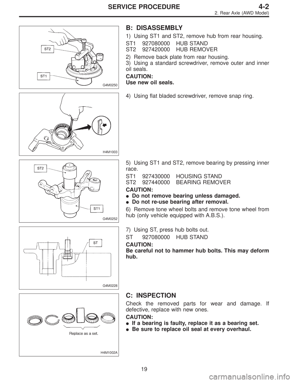
1) Using ST1 and ST2, remove hub from rear housing.
ST1 927080000 HUB STAND
ST2 927420000 HUB REMOVER
2) Remove back plate from rear housing.
3) Using a standard screwdriver, remove outer and inner
oil seals.
CAUTION:
Use new oil seals.
H4M1003
4) Using flat bladed screwdriver, remove snap ring.
G4M0252
5) Using ST1 and ST2, remove bearing by pressing inner
race.
ST1 927430000 HOUSING STAND
ST2 927440000 BEARING REMOVER
CAUTION:
�Do not remove bearing unless damaged.
�Do not re-use bearing after removal.
6) Remove tone wheel bolts and remove tone wheel from
hub (only vehicle equipped with A.B.S.).
G4M0228
7) Using ST, press hub bolts out.
ST 927080000 HUB STAND
CAUTION:
Be careful not to hammer hub bolts. This may deform
hub.
H4M1002A
C: INSPECTION
Check the removed parts for wear and damage. If
defective, replace with new ones.
CAUTION:
�If a bearing is faulty, replace it as a bearing set.
�Be sure to replace oil seal at every overhaul.
19
4-2SERVICE PROCEDURE
2. Rear Axle (AWD Model)
Page 1074 of 2890
G4M0271
NOTE:
If brake drum seizes up within hub, drive it out by installing
an 8-mm bolt in bolt hole on brake drum.
12) Disconnect end of parking brake cable.
13) Using a flare-nut wrench, disconnect brake pipe from
wheel cylinder.
CAUTION:
Cover brake pipe connection to prevent entry of for-
eign particles.
G4M0273
14) Remove bolts which secure trailing link assembly to
rear spindle.
CAUTION:
Discard old self-locking nut. Replace with a new one.
G4M0272
15) Remove bolts which secure lateral link assembly to
rear spindle.
CAUTION:
Discard old self-locking nut. Replace with a new one.
G4M0249
16) Remove bolts which secure strut assembly to rear
spindle.
Remove rear spindle, back plate and hub as a unit.
G4M0275
B: DISASSEMBLY
1) Remove hub from rear spindle.
25
4-2SERVICE PROCEDURE
3. Rear Axle (FWD Model)
Page 1079 of 2890
G4M0216
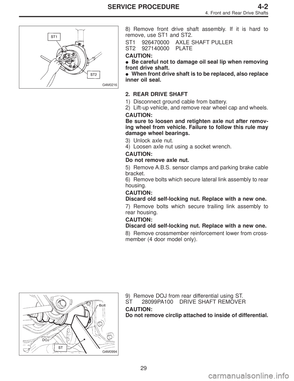
8) Remove front drive shaft assembly. If it is hard to
remove, use ST1 and ST2.
ST1 926470000 AXLE SHAFT PULLER
ST2 927140000 PLATE
CAUTION:
�Be careful not to damage oil seal lip when removing
front drive shaft.
�When front drive shaft is to be replaced, also replace
inner oil seal.
2. REAR DRIVE SHAFT
1) Disconnect ground cable from battery.
2) Lift-up vehicle, and remove rear wheel cap and wheels.
CAUTION:
Be sure to loosen and retighten axle nut after remov-
ing wheel from vehicle. Failure to follow this rule may
damage wheel bearings.
3) Unlock axle nut.
4) Loosen axle nut using a socket wrench.
CAUTION:
Do not remove axle nut.
5) Remove A.B.S. sensor clamps and parking brake cable
bracket.
6) Remove bolts which secure lateral link assembly to rear
housing.
CAUTION:
Discard old self-locking nut. Replace with a new one.
7) Remove bolts which secure trailing link assembly to
rear housing.
CAUTION:
Discard old self-locking nut. Replace with a new one.
8) Remove crossmember reinforcement lower from cross-
member (4 door model only).
G4M0994
9) Remove DOJ from rear differential using ST.
ST 28099PA100 DRIVE SHAFT REMOVER
CAUTION:
Do not remove circlip attached to inside of differential.
29
4-2SERVICE PROCEDURE
4. Front and Rear Drive Shafts
Page 1097 of 2890
6. Replacement of Rear DOJ and BJ
Boots
A: REMOVAL
1) Disconnect ground cable from battery.
2) Lift-up vehicle, and remove rear wheel cap and wheels.
NOTE:
Axle nut need not be removed.
3) Remove A.B.S. sensor clamps and parking brake cable
bracket.
4) Disconnect stabilizer link from lateral link.
5) Remove bolts which secure lateral link assembly to rear
housing.
6) Remove bolts which secure trailing link assembly to
rear housing.
7) Remove crossmember reinforcement lower from cross-
member (4 door model only).
G4M0994
8) Remove DOJ from rear differential using ST.
ST 28099PA100 DRIVE SHAFT REMOVER
NOTE:
The side spline shaft circlip comes out together with the
shaft.
G4M0995
CAUTION:
Be careful not to damage side bearing retainer. Always
use bolt as shown in figure, as supporting point for ST
during removal.
ST 28099PA100 DRIVE SHAFT REMOVER
B: INSTALLATION
1) Install DOJ and BJ boots to drive shaft.
47
4-2SERVICE PROCEDURE
6. Replacement of Rear DOJ and BJ Boots
Page 1103 of 2890
B4M0053A
10. Wheel Balancing
1) Proper wheel balance may be lost if the tire is repaired
or if it wears. Check the tire for dynamic balance, and repair
as necessary.
2) To check for dynamic balance, use a dynamic balancer.
Drive in the balance weight on both the top and rear sides
of the rim.
3) Some types of balancer can cause damage to the
wheel. Use an appropriate balancer when adjusting the
wheel balance.
4) Use genuine balance weights.
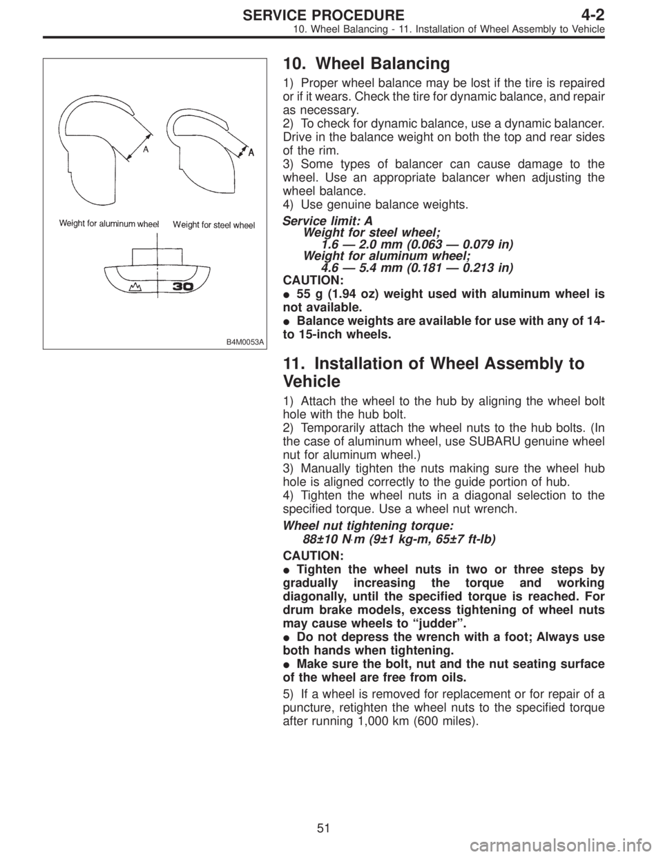
Service limit: A
Weight for steel wheel;
1.6—2.0 mm (0.063—0.079 in)
Weight for aluminum wheel;
4.6—5.4 mm (0.181—0.213 in)
CAUTION:
�55 g (1.94 oz) weight used with aluminum wheel is
not available.
�Balance weights are available for use with any of 14-
to 15-inch wheels.
11. Installation of Wheel Assembly to
Vehicle
1) Attach the wheel to the hub by aligning the wheel bolt
hole with the hub bolt.
2) Temporarily attach the wheel nuts to the hub bolts. (In
the case of aluminum wheel, use SUBARU genuine wheel
nut for aluminum wheel.)
3) Manually tighten the nuts making sure the wheel hub
hole is aligned correctly to the guide portion of hub.
4) Tighten the wheel nuts in a diagonal selection to the
specified torque. Use a wheel nut wrench.
Wheel nut tightening torque:
88±10 N⋅m (9±1 kg-m, 65±7 ft-lb)
CAUTION:
�Tighten the wheel nuts in two or three steps by
gradually increasing the torque and working
diagonally, until the specified torque is reached. For
drum brake models, excess tightening of wheel nuts
may cause wheels to “judder”.
�Do not depress the wrench with a foot; Always use
both hands when tightening.
�Make sure the bolt, nut and the nut seating surface
of the wheel are free from oils.
5) If a wheel is removed for replacement or for repair of a
puncture, retighten the wheel nuts to the specified torque
after running 1,000 km (600 miles).
51
4-2SERVICE PROCEDURE
10. Wheel Balancing - 11. Installation of Wheel Assembly to Vehicle
Page 1104 of 2890
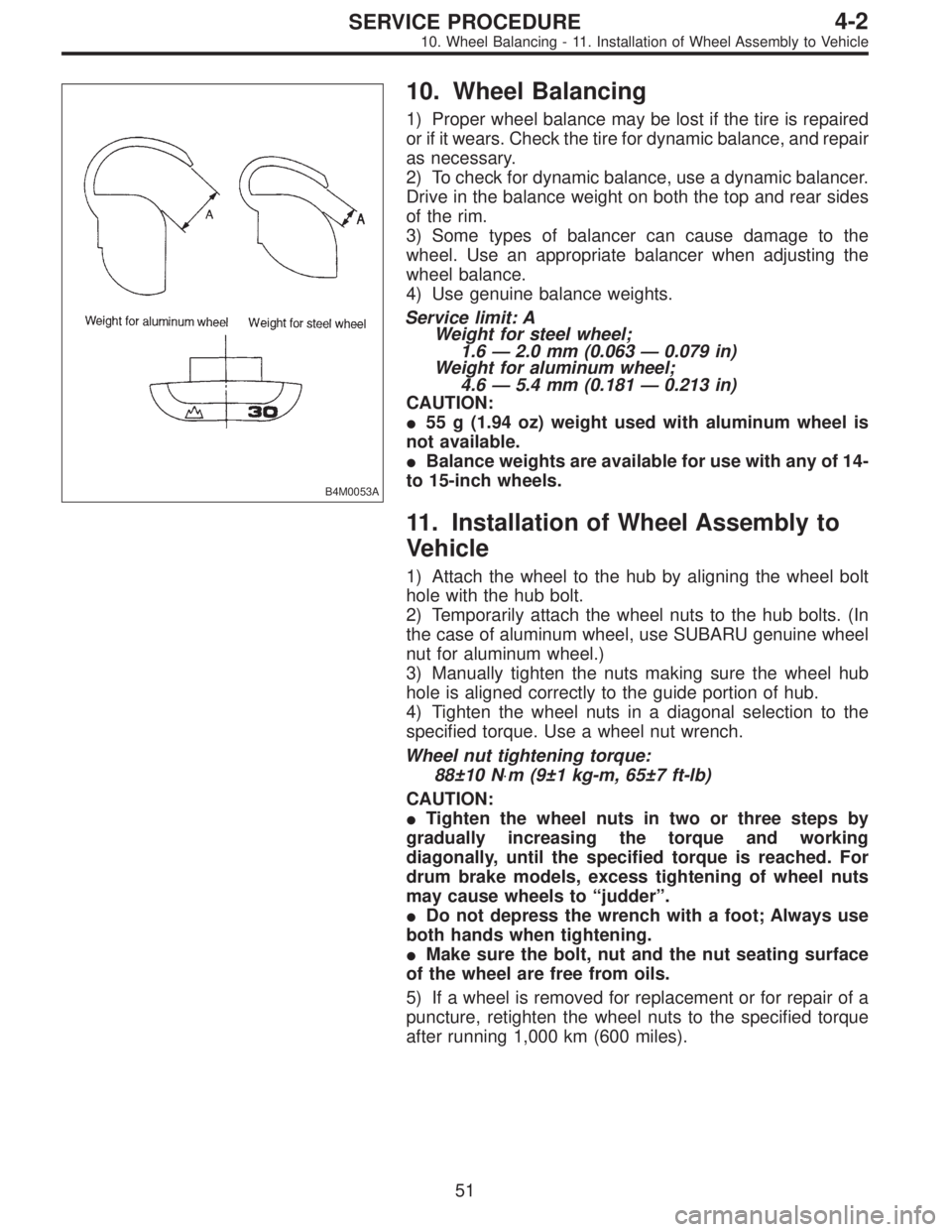
B4M0053A
10. Wheel Balancing
1) Proper wheel balance may be lost if the tire is repaired
or if it wears. Check the tire for dynamic balance, and repair
as necessary.
2) To check for dynamic balance, use a dynamic balancer.
Drive in the balance weight on both the top and rear sides
of the rim.
3) Some types of balancer can cause damage to the
wheel. Use an appropriate balancer when adjusting the
wheel balance.
4) Use genuine balance weights.
Service limit: A
Weight for steel wheel;
1.6—2.0 mm (0.063—0.079 in)
Weight for aluminum wheel;
4.6—5.4 mm (0.181—0.213 in)
CAUTION:
�55 g (1.94 oz) weight used with aluminum wheel is
not available.
�Balance weights are available for use with any of 14-
to 15-inch wheels.
11. Installation of Wheel Assembly to
Vehicle
1) Attach the wheel to the hub by aligning the wheel bolt
hole with the hub bolt.
2) Temporarily attach the wheel nuts to the hub bolts. (In
the case of aluminum wheel, use SUBARU genuine wheel
nut for aluminum wheel.)
3) Manually tighten the nuts making sure the wheel hub
hole is aligned correctly to the guide portion of hub.
4) Tighten the wheel nuts in a diagonal selection to the
specified torque. Use a wheel nut wrench.
Wheel nut tightening torque:
88±10 N⋅m (9±1 kg-m, 65±7 ft-lb)
CAUTION:
�Tighten the wheel nuts in two or three steps by
gradually increasing the torque and working
diagonally, until the specified torque is reached. For
drum brake models, excess tightening of wheel nuts
may cause wheels to “judder”.
�Do not depress the wrench with a foot; Always use
both hands when tightening.
�Make sure the bolt, nut and the nut seating surface
of the wheel are free from oils.
5) If a wheel is removed for replacement or for repair of a
puncture, retighten the wheel nuts to the specified torque
after running 1,000 km (600 miles).
51
4-2SERVICE PROCEDURE
10. Wheel Balancing - 11. Installation of Wheel Assembly to Vehicle
Page 1118 of 2890
G5M0332
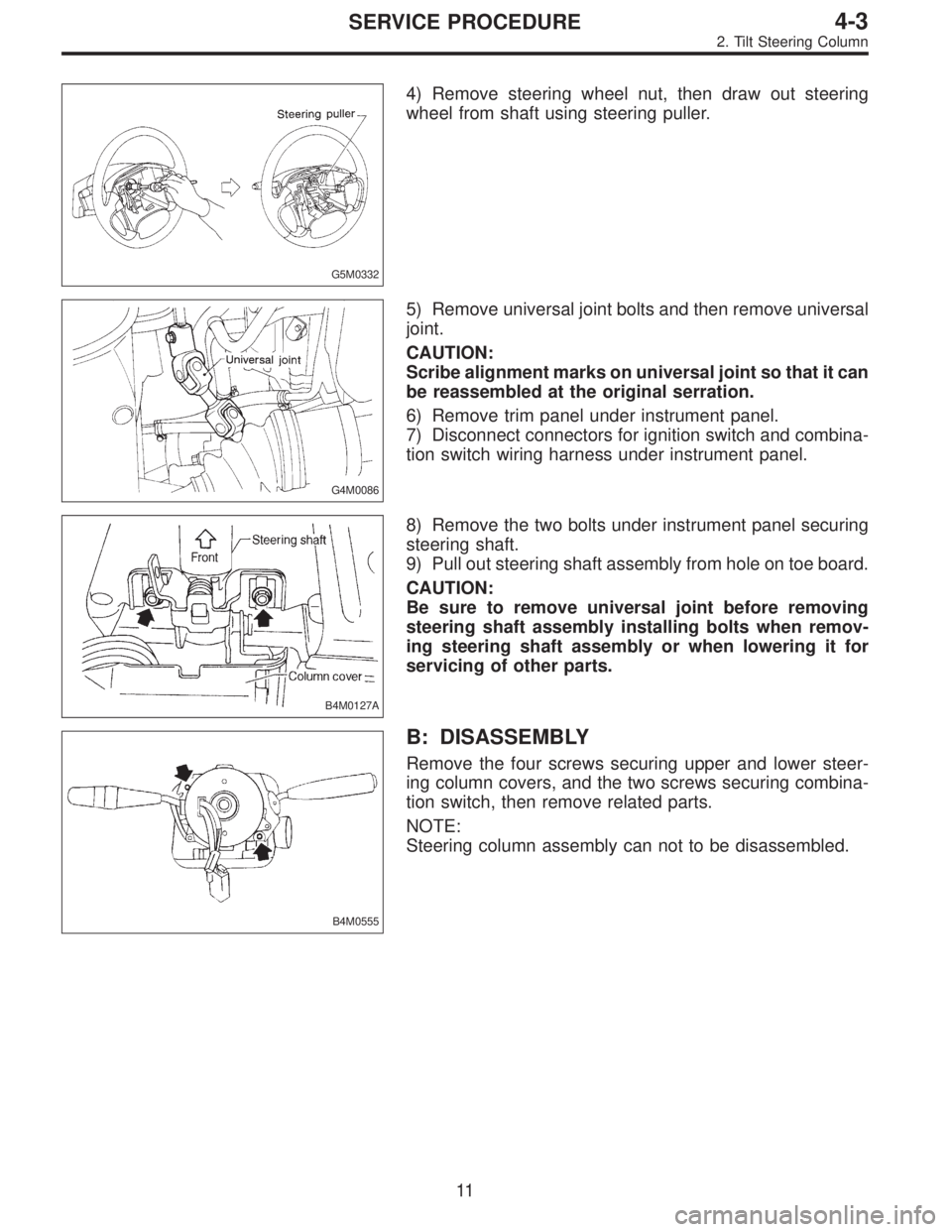
4) Remove steering wheel nut, then draw out steering
wheel from shaft using steering puller.
G4M0086
5) Remove universal joint bolts and then remove universal
joint.
CAUTION:
Scribe alignment marks on universal joint so that it can
be reassembled at the original serration.
6) Remove trim panel under instrument panel.
7) Disconnect connectors for ignition switch and combina-
tion switch wiring harness under instrument panel.
B4M0127A
8) Remove the two bolts under instrument panel securing
steering shaft.
9) Pull out steering shaft assembly from hole on toe board.
CAUTION:
Be sure to remove universal joint before removing
steering shaft assembly installing bolts when remov-
ing steering shaft assembly or when lowering it for
servicing of other parts.
B4M0555
B: DISASSEMBLY
Remove the four screws securing upper and lower steer-
ing column covers, and the two screws securing combina-
tion switch, then remove related parts.
NOTE:
Steering column assembly can not to be disassembled.
11
4-3SERVICE PROCEDURE
2. Tilt Steering Column