Page 293 of 2890

B2M0955A
B: INSTALLATION
CAUTION:
Leave fuel filler cap open when tightening nuts, to pre-
vent fuel from flowing out through fuel delivery and
return pipes. Close fuel filler cap after tightening nuts.
Installation is in the reverse order of removal. Do the fol-
lowing:
(1) Always use new gaskets.
(2) Ensure sealing portion is free from fuel or foreign
particles before installation.
(3) Tighten nuts in numerical sequence shown in Fig-
ure to specified torque.
Tightening torque:
4.4±1.5 N⋅m (0.45±0.15 kg-m, 3.3±1.1 ft-lb)
G6M0095
9. Fuel Tank Pressure Sensor (2200 cc
AWD Model)
A: REMOVAL AND INSTALLATION
1) Disconnect battery ground cable.
H2M1122B
2) Remove trims.
�4 door model:
Remove right trunk side trim.
B2M0927A
�Wagon model:
(1) Remove right rear quarter upper rear trim.
(2) Remove right strut cap.
(3) Remove right rear quarter pillar lower trim.
11
2-1SERVICE PROCEDURE
8. Fuel Temperature Sensor (2200 cc AWD Model) - 9. Fuel Tank Pressure Sensor (2200 cc AWD Model)
Page 294 of 2890

B2M0955A
B: INSTALLATION
CAUTION:
Leave fuel filler cap open when tightening nuts, to pre-
vent fuel from flowing out through fuel delivery and
return pipes. Close fuel filler cap after tightening nuts.
Installation is in the reverse order of removal. Do the fol-
lowing:
(1) Always use new gaskets.
(2) Ensure sealing portion is free from fuel or foreign
particles before installation.
(3) Tighten nuts in numerical sequence shown in Fig-
ure to specified torque.
Tightening torque:
4.4±1.5 N⋅m (0.45±0.15 kg-m, 3.3±1.1 ft-lb)
G6M0095
9. Fuel Tank Pressure Sensor (2200 cc
AWD Model)
A: REMOVAL AND INSTALLATION
1) Disconnect battery ground cable.
H2M1122B
2) Remove trims.
�4 door model:
Remove right trunk side trim.
B2M0927A
�Wagon model:
(1) Remove right rear quarter upper rear trim.
(2) Remove right strut cap.
(3) Remove right rear quarter pillar lower trim.
11
2-1SERVICE PROCEDURE
8. Fuel Temperature Sensor (2200 cc AWD Model) - 9. Fuel Tank Pressure Sensor (2200 cc AWD Model)
Page 1449 of 2890
5. TRUNK LID AND REAR GATE
B5M0255A
Unit: mm (in)
20
5-1SERVICE DATA
3. Datum Dimensions
Page 1453 of 2890
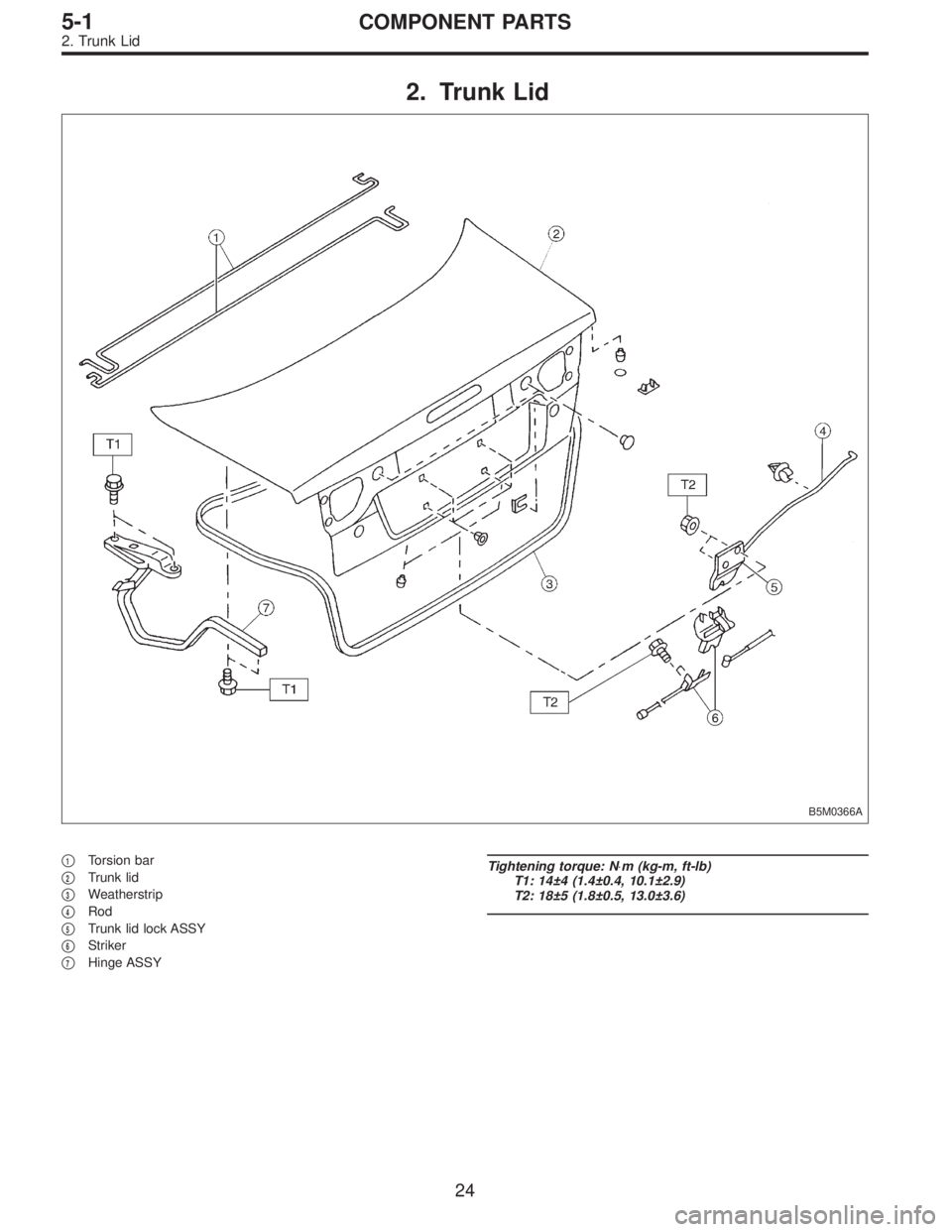
2. Trunk Lid
B5M0366A
�1Torsion bar
�
2Trunk lid
�
3Weatherstrip
�
4Rod
�
5Trunk lid lock ASSY
�
6Striker
�
7Hinge ASSY
Tightening torque: N⋅m (kg-m, ft-lb)
T1: 14±4 (1.4±0.4, 10.1±2.9)
T2: 18±5 (1.8±0.5, 13.0±3.6)
24
5-1COMPONENT PARTS
2. Trunk Lid
Page 1464 of 2890
G5M0144
2. Trunk Lid
A: REMOVAL
1. TRUNK LID
1) Open trunk lid.
2) Remove trunk lid mounting bolts and detach trunk lid
from hinges.
G5M0145
2. TORSION BAR
1) Open trunk lid. Remove torsion bars from hinge links
using ST.
ST 927780000 REMOVER
CAUTION:
Be careful because torsion bar quickly swings back
when released.
2) Remove the left and right torsion bars.
WARNING:
Be careful because trunk lid drops under its own
weight when torsion bars are removed.
G5M0146
3. TRUNK LID LOCK ASSEMBLY AND KEY
CYLINDER
1) Remove rod of lock assembly from rod holder of key
lock assembly.
2) Remove nuts which hold lock assembly and remove
lock assembly.
NOTE:
�Always remove rear skirt trim panel beforehand, if so
equipped.
�Be careful not to bend opener cable.
B5M0269A
3) Remove rod holder and detach key cylinder from trunk
lid.
35
5-1SERVICE PROCEDURE
2. Trunk Lid
Page 1465 of 2890
 Remove rear seats, center pillar lower cover, floor mat,
rear arch cover and side sill cover (on the driver’s side).
2) Remove all clips which hold cable.
3) Disconnec")
G5M0147
4. TRUNK LID OPENER
1) Remove rear seats, center pillar lower cover, floor mat,
rear arch cover and side sill cover (on the driver’s side).
2) Remove all clips which hold cable.
3) Disconnect cable from pull handle assembly.
4) Remove bolts and detach pull handle assembly.
5) Loosen bolts which hold lock assembly, and remove it.
6) Remove striker from trunk lid.
7) Disconnect cable from striker.
NOTE:
�Be careful not to bend or break cable.
�Basic model vehicles do not have trunk lid opener sys-
tem.
B5M0372A
B: INSTALLATION
Installation is in the reverse order of removal.
CAUTION:
�When installing cover to pull handle assembly,
observe the following:
�Be careful not to catch harness.
�Engage pull handle assembly pawls firmly.
�After installing opener cable, ensure it moves
smoothly.
�Apply a coat of grease to the rotary section of
hinges and contact surfaces of torsion bars.
�Apply grease to sliding surfaces of lock assembly
and striker.
B5M0270A
C: ADJUSTMENT
1. TRUNK LID
1) To adjust left-right lid positioning, loosen bolts which
hold trunk lid to hinges.
2) To adjust up-down lid alignment, place washer(s)
between trunk lid and hinges or move trunk lock assembly
up or down.
36
5-1SERVICE PROCEDURE
2. Trunk Lid
Page 1471 of 2890
B5M0377
5. Rear Bumper
A: REMOVAL
1. SEDAN
1) Remove one bolt and one clip from side of bumper.
2) Open trunk lid. Remove trunk trim panel clips and
detach trim.
B5M0378
3) Remove rear bumper beam (upper) attaching nut.
4) Remove bolts from bumper stays.
B5M0280
5) Remove rear bumper assembly.
B5M0377
2. WAGON
1) Remove one bolt and one clip from side of bumper.
2) Open rear gate. Remove rear quarter trim lid.
B5M0379
3) Remove two clips from lower center of bumper.
42
5-1SERVICE PROCEDURE
5. Rear Bumper
Page 1496 of 2890
B5M0413
19. Rear Spoiler (4 Door Sedan 2500 cc
GT model only)
A: REMOVAL AND INSTALLATION
1) Open trunk lid.
2) Disconnect high-mount stop light connector located
inside the trunk lid.
3) Remove rubber caps.
B5M0414
4) Remove rear spoiler mounting nuts.
CAUTION:
When removing nuts, be careful not to drop them
inside rear gate.
5) Installation is in the reverse order of removal.
Tightening torque:
7.4±2.0 N⋅m (0.75±0.2 kg-m, 5.4±1.4 ft-lb)
B5M0305
20. Roof Spoiler (Station Wagon 2500
cc GT model only)
A: REMOVAL AND INSTALLATION
1) Open rear gate and remove rear gate trim upper and
side.
2) Remove high-mount stop light.
B5M0415A
3) Remove plastic caps and harness covers.
62
5-1SERVICE PROCEDURE
19. Rear Spoiler (4 Door Sedan 2500 cc GT model only) - 20. Roof Spoiler (Station Wagon 2500 cc GT model only)

20
5-1SERVICE DATA
3. Datum Dimensions")
 Open trunk lid.
2) Remove trunk lid mounting bolts and detach trunk lid
from hinges.
G5M0145
2. TORSION BAR
1) Open trunk lid. Remove torsion bars from")
 Remove one bolt and one clip from side of bumper.
2) Open trunk lid. Remove trunk trim panel clips and
detach trim.
B5M0378
3) Remove rear bumper beam (up")

A: REMOVAL AND INSTALLATION
1) Open trunk lid.
2) Disconnect high-mount stop light connector located
inside the trunk lid.
3) Remove rubbe")