Page 1717 of 2890
 Remove door trim panel a")
B6M0364A
4. KEY CYLINDER LOCK/UNLOCK SWITCH AND
TAMPER SWITCH
NOTE:
The key cylinder lock switch, unlock switch and tamper
switch are united in the switch body.
Door Switch
1) Remove door trim panel and sealing cover.
[W2A3].>
2) Disconnect connector of door key cylinder switch from
door cord.
3) Remove door outer handle.
CAUTION:
Be careful not to damage the door surface.
4) Remove clip, and then remove door key cylinder switch
from door outer handle.
5) Installation is in the reverse order of removal.
Trunk Lid Switch (SEDAN)
1) Disconnect connector of trunk lid key cylinder switch.
2) Disconnect rod from key cylinder.
3) Remove trunk lid key cylinder switch by pushing it.
4) Installation is in the reverse order of removal.
B6M0368A
Rear Gate Switch (WAGON)
1) Disconnect connector of rear gate key cylinder switch.
2) Disconnect rod from key cylinder.
3) Remove attaching bolts, and then remove rear gate key
cylinder switch.
4) Installation is in the reverse order of removal.
5. DOOR LOCK/UNLOCK SWITCH
NOTE:
The door lock/unlock switch is united with the power door
lock actuator.
Driver and Passenger Door
1) Remove door trim panel and sealing cover.
[W2A3].>
2) Disconnect connector of door lock actuator assembly
from door code.
53
6-2SERVICE PROCEDURE
22. Security System
Page 1718 of 2890
![SUBARU LEGACY 1996 Service Repair Manual 3) Remove door lock actuator assembly. <Ref. to 5-2
[W2A7].>
4) Installation is in the reverse order of removal.
Rear Gate (WAGON)
1) Remove rear gate trim panel.
2) Disconnect rod from rear gate latc](/manual-img/17/57433/w960_57433-1717.png "SUBARU LEGACY 1996 Service Repair Manual 3) Remove door lock actuator assembly. <Ref. to 5-2
[W2A7].>
4) Installation is in the reverse order of removal.
Rear Gate (WAGON)
1) Remove rear gate trim panel.
2) Disconnect rod from rear gate latc")
3) Remove door lock actuator assembly.
[W2A7].>
4) Installation is in the reverse order of removal.
Rear Gate (WAGON)
1) Remove rear gate trim panel.
2) Disconnect rod from rear gate latch assembly.
3) Disconnect rear gate switch connector and power door
lock actuator connector.
4) Remove bolts which secure power door lock actuator.
5) Remove bolts which secure latch.
6) Remove latch and actuator assembly.
7) Installation is in the reverse order of removal.
B6M0070A
6. DOOR SWITCH
1) Remove rubber boot of door switch.
2) Remove screw which secures door switch to body.
3) Remove door switch while disconnecting connector.
B6M0371A
7. TRUNK LID SWITCH (SEDAN)
NOTE:
The trunk lid switch is united with the trunk lid lock.
1) Remove trunk rear trim.
2) Disconnect connector of trunk switch (combined with
trunk room light switch).
3) Put matching mark on the trunk lid lock and vehicle
body before removal.
4) Remove bolts, then remove trunk lid lock from vehicle
body.
5) Installation is in the reverse order of removal.
NOTE:
Ensure that matching mark is aligned between trunk lid
lock and vehicle body.
54
6-2SERVICE PROCEDURE
22. Security System
Page 1721 of 2890
B6M0377
4. KEY CYLINDER LOCK/UNLOCK SWITCH AND
TAMPER SWITCH
Door Switch
1) Disconnect connector of door key cylinder switch.
2) Move switch by turning the key cylinder with ignition key
and/or remove switch from key cylinder to check continuity
between terminals as indicated in table below:
Terminal
Switch position1234
Normal
LOCK��
UNLOCK��
Switch is removed from
key cylinder.��
B6M0378A
Trunk Lid Switch (SEDAN)
1) Disconnect connector of trunk lid key cylinder switch.
2) Move switch by turning the key cylinder with ignition key
and/or remove switch from key cylinder to check continuity
between terminals as indicated in table below:
Terminal
Switch position123
Normal
UNLOCK��
Switch is removed from
key cylinder.��
57
6-2SERVICE PROCEDURE
22. Security System
Page 1723 of 2890
6. DOOR SWITCH
Refer to 6-2 [W8B1] as for inspection of door switch.
NOTE:
The door switch is combined with the door switch for room
light.
7. TRUNK LID SWITCH (SEDAN)
Refer to 6-2 [W8B2] as for inspection of trunk lid switch.
NOTE:
The trunk lid switch is combined with the trunk room light
switch.
8. REAR GATE SWITCH (WAGON)
Refer to 6-2 [W8B3] as for inspection of rear gate switch.
NOTE:
The rear gate switch is combined with the luggage room
light switch.
B6M0382A
9. SECURITY INDICATOR LIGHT
1) Remove security indicator light.
2) Check continuity between terminals of security indicator
light.
3) If there is no continuity, the indicator light will be fail-
ured.
Terminals: No. 2—No. 4
10. SECURITY CONTROL MODULE
Refer to 6-2 [K600]:“6. SECURITY SYSTEM”for inspec-
tion of security control module.
59
6-2SERVICE PROCEDURE
22. Security System
Page 1725 of 2890
 Within 30 seconds after the above step 13), pull the
trunk lid opener lever and open the trunk lid (SEDAN); or
unlock the rear gate by operating the driver’s door inside
lock knob and open the r")
14) Within 30 seconds after the above step 13), pull the
trunk lid opener lever and open the trunk lid (SEDAN); or
unlock the rear gate by operating the driver’s door inside
lock knob and open the rear gate (WAGON).
Check that the security indicator light flashes at 0.5 sec.
intervals.
15) Close the trunk lid completely (SEDAN); or close the
rear gate and lock by locking the driver’s door using a igni-
tion key (WAGON).
Check that the security indicator light illuminates continu-
ously.
16) When the security indicator light illuminates
continuously, wait for 30 seconds.
After 30 seconds, check that the light starts repeating 0.2
sec. ON and 2.4 sec. OFF sequence.
17) Unlock the trunk lid (SEDAN) or rear gate (WAGON)
using a ignition key and open.
Check that the horn and headlights do not operate.
18) Close the trunk lid (SEDAN) or rear gate (WAGON).
19) Unlock and then lock the driver’s door using a ignition
key and wait for 30 seconds.
After 30 seconds, check that the light starts repeating 0.2
sec. ON and 2.4 sec. OFF sequence.
20) Only WAGON model; unlock and then lock the rear
gate using a ignition key and wait for 30 seconds.
After 30 seconds, check that the light starts repeating 0.2
sec. ON and 2.4 sec. OFF sequence.
21) Unlock the front RH door using a ignition key and open
the door.
Check that the horn and headlights do not operate.
After finishing the above checks, ensure that security sys-
tem’s function is correct.
61
6-2SERVICE PROCEDURE
22. Security System
Page 1749 of 2890
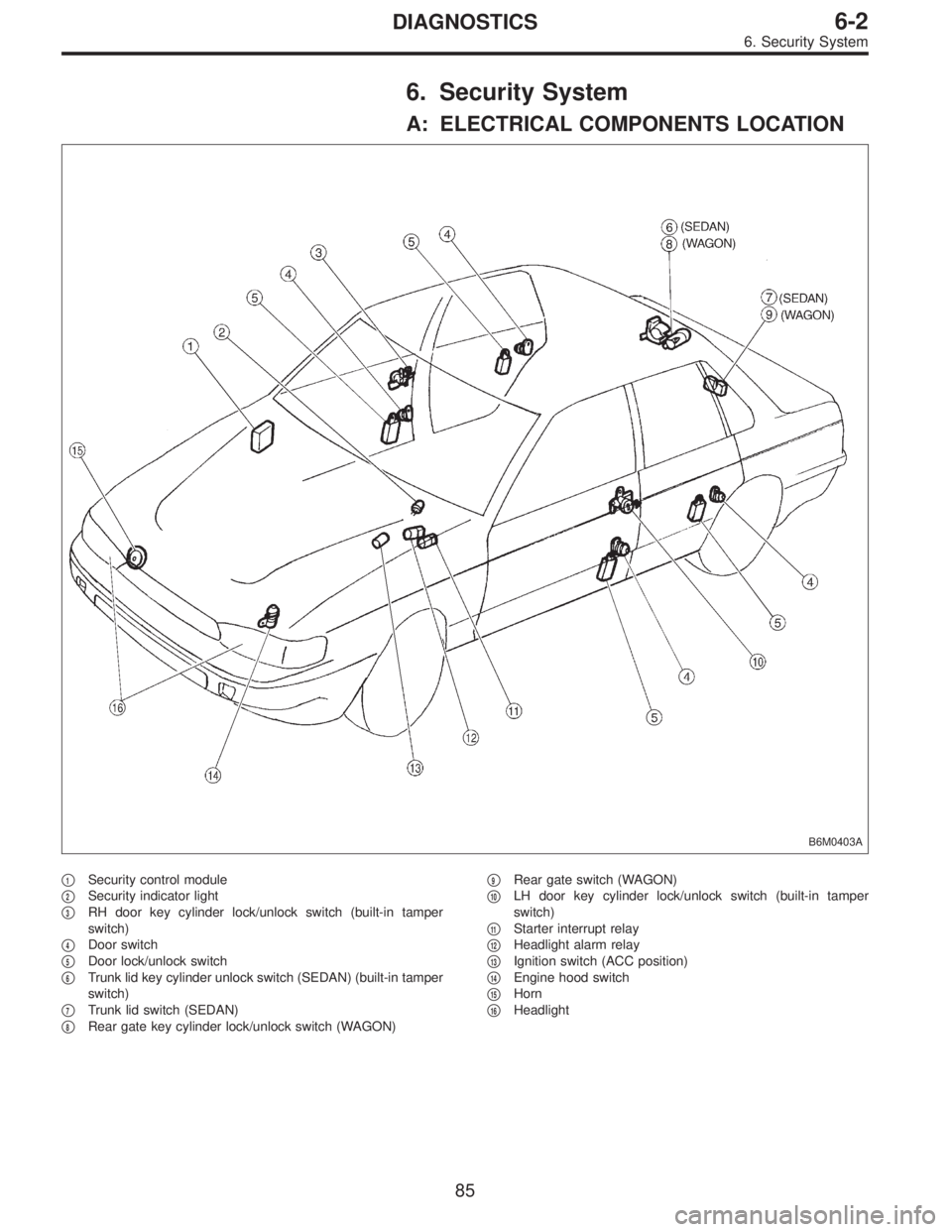
6. Security System
A: ELECTRICAL COMPONENTS LOCATION
B6M0403A
�1Security control module
�
2Security indicator light
�
3RH door key cylinder lock/unlock switch (built-in tamper
switch)
�
4Door switch
�
5Door lock/unlock switch
�
6Trunk lid key cylinder unlock switch (SEDAN) (built-in tamper
switch)
�
7Trunk lid switch (SEDAN)
�
8Rear gate key cylinder lock/unlock switch (WAGON)�
9Rear gate switch (WAGON)
�
10LH door key cylinder lock/unlock switch (built-in tamper
switch)
�
11Starter interrupt relay
�
12Headlight alarm relay
�
13Ignition switch (ACC position)
�
14Engine hood switch
�
15Horn
�
16Headlight
85
6-2DIAGNOSTICS
6. Security System
Page 1751 of 2890

Door lock/unlock switch1
(INPUT)�Battery voltage is present when all doors")
C: CONTROL MODULE I/O SIGNAL
B6M0405
Content Terminal No.Measuring conditions and I/O signals
(Ignition switch ACC position)
Door lock/unlock switch1
(INPUT)�Battery voltage is present when all doors and rear gate (WAGON) are locked.
�“0”volt is present when one of the doors or rear gate (WAGON) is unlocked.
Key cylinder lock switch2
(INPUT)�“0”volt is present when key cylinder is turned to LOCK position.
�Battery voltage is present when key cylinder is in positions other than LOCK.
Tamper switch3
(INPUT)�Battery voltage is present when key cylinder switch is installed to key cylinder.
�“0”volt is present when key cylinder switch is removed from key cylinder.
Door switch4
(INPUT)�Battery voltage is present when all doors are closed.
�“0”volt is present when one of the doors is open.
Starter interrupt relay5
(OUTPUT)�Battery voltage is present when ignition switch is turned ACC or ON.
�“0”volt is present when security system is in alarm state.
Ignition switch (ACC)6
(INPUT)�Battery voltage is present when ignition switch is turned ACC or ON.
�“0”volt is present when ignition switch is turned OFF.
Security indicator light7
(OUTPUT)�Battery voltage is present when indicator light goes off.
�“0”volt is present when indicator light illuminates.
Power supply (back-up) 8 Battery voltage is constantly present.
Ground 9—
Engine hood switch10
(INPUT)�Battery voltage is present when engine hood is closed.
�“0”volt is present when engine hood is open.
Trunk lid switch (SEDAN)
Rear gate switch (WAGON)11
(INPUT)�Battery voltage is present when trunk lid or rear gate is closed.
�“0”volt is present when trunk lid or rear gate is open.
Headlight alarm relay12
(OUTPUT)�Battery voltage is present when ignition switch is turned ACC or ON.
�“0”volt and battery voltage repeats in alarm state. (Headlights flash intermittently
at 0.2 sec. ON and 0.6 sec. OFF intervals).
Horn relay13
(OUTPUT)�Battery voltage is present when ignition switch is turned ACC or ON.
�“0”volt and battery voltage repeats in alarm state. (Horn sounds intermittently at
0.2 sec. ON and 0.6 sec. OFF intervals.)
Key cylinder unlock switch14
(INPUT)�“0”volt is present when key cylinder is turned to UNLOCK position.
�Battery voltage is present when key cylinder is in positions other than UNLOCK.
Trunk lid key cylinder unlock
switch (SEDAN)15
(INPUT)�“0”volt is present when trunk lid key cylinder is turned to UNLOCK position.
�Battery voltage is present when trunk lid key cylinder is in positions other than
UNLOCK.
87
6-2DIAGNOSTICS
6. Security System
Page 1752 of 2890

D: BASIC DIAGNOSTICS PROCEDURE
Start security system check.
Fully open all door windows and turn ignition switch OFF.
Take key out of ignition, exit vehicle and lock driver’s door.
Indicator light illuminates.
OK The light flashes.
� The light does not
illuminate.
Check indicator harness.
Check security indicator light.
Check driver’s door key cylinder lock/unlock switch.
Check security control module.
Check whether switch input signal remains UNLOCK.
Check wiring harness.
Check switch input signals.
(Harnesses and switches separately)
(Tamper, door, hood, trunk and rear gate
switch)Check security control module.
Wait for 30 seconds.
Indicator light flashes at long intervals (0.2 sec. ON and 2.4 sec.
OFF).
OK
� Not OK
Check security control module.
Unlock driver’s door using the inside lock knob and open door.
The horn sounds and headlights flash intermittently at 0.2 sec. ON
and 0.6 sec. OFF intervals.
The engine will not start even if the ignition switch is turned to
START. Indicator lamp goes out.
OK Starter motor runs.
� All are not OK.
Check driver’s door switch.
Check wiring harness.
Check security control module.
� Horn is not OK.
Check horn
operation by
pushing horn pad
on steering wheel.
OK
� Not OK
Check horn.
Check horn relay.
Check security control module.
Check harness between horn relay and security control module.
� Headlights are not
OK.
Check headlights
operation by
turning light switch
ON/OFF.
OK
� Not OK
Check headlight
bulbs.
Check combination
switch.
Check headlight
relay.
Check starter interrupt relay.
Check wiring harness.
Check security control module.Check headlight alarm relay.
Check security control module.
Check wiring harness.
The alarm system continues to operate for 150 seconds.
OK Not OK
The horn and
headlights turn off.
The starter motor
does not run.
OK
� Not OK
Check security
control module.
Unlock the driver’s door using ignition key.
Continues to next step.
�
�
�
�
�
�
�
�
�
��
�
��
�
�
88
6-2DIAGNOSTICS
6. Security System
 Disconnect connector of door key cylinder switch.
2) Move switch by turning the key cylinder with ignition key
and/or remove")
![SUBARU LEGACY 1996 Service Repair Manual 6. DOOR SWITCH
Refer to 6-2 [W8B1] as for inspection of door switch.
NOTE:
The door switch is combined with the door switch for room
light.
7. TRUNK LID SWITCH (SEDAN)
Refer to 6-2 [W8B2] as for inspe](/manual-img/17/57433/w960_57433-1722.png "SUBARU LEGACY 1996 Service Repair Manual 6. DOOR SWITCH
Refer to 6-2 [W8B1] as for inspection of door switch.
NOTE:
The door switch is combined with the door switch for room
light.
7. TRUNK LID SWITCH (SEDAN)
Refer to 6-2 [W8B2] as for inspe")