Page 1038 of 2890
G4M0533
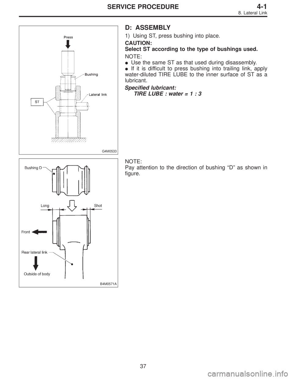
D: ASSEMBLY
1) Using ST, press bushing into place.
CAUTION:
Select ST according to the type of bushings used.
NOTE:
�Use the same ST as that used during disassembly.
�If it is difficult to press bushing into trailing link, apply
water-diluted TIRE LUBE to the inner surface of ST as a
lubricant.
Specified lubricant:
TIRE LUBE : water=1:3
B4M0571A
NOTE:
Pay attention to the direction of bushing“D”as shown in
figure.
37
4-1SERVICE PROCEDURE
8. Lateral Link
Page 1049 of 2890
G4M0208
1. Wheels and Axles
A: SPECIFICATIONS
1. TIRE AND WHEEL SIZE
Tire size Rim sizeRim offset
mm (in)P.C.D.
mm (in)
Except OUTBACK modelFront and RearP185/70R14
87S14×5 1/2JJ 55 (2.17)
100 (3.94)
dia. P195/60R15
87H15 x 6JJ 55 (2.17)
T-type tireT125/70D15 15 x 4T 53 (2.09)
T135/70D16 16 x 4T 50 (1.97)
OUTBACK modelFront and RearP205/70R15
95S15 x 6JJ 55 (2.17)
T-type tire T135/80D16 16 x 4T 50 (1.97)
NOTE:“T-type”tire for temporary use is supplied as a spare tire.
2. TIRE INFLATION PRESSURE
Tire sizeTire inflation pressure kPa (kg/cm
2, psi)
Light load Full load Trailler towing
Except OUTBACK
modelFront and RearP185/70R14 87S
P195/60R15 87HFt: 220 (2.2, 32)
Rr: 210 (2.1, 30)—
T-type tireT125/70D15
T135/70D16420 (4.2, 60)
OUTBACK modelFront and Rear P205/70R15 95SFt: 200 (2.0, 29)
Rr: 190 (1.9, 28)Ft: 200 (2.0, 2.9)
Rr: 220 (2.2, 32)
T-type tire T135/80D16 420 (4.2, 60)
2
4-2SPECIFICATIONS AND SERVICE DATA
1. Wheels and Axles
Page 1103 of 2890
 Proper wheel balance may be lost if the tire is repaired
or if it wears. Check the tire for dynamic balance, and repair
as necessary.
2) To check for dynamic balance, u")
B4M0053A
10. Wheel Balancing
1) Proper wheel balance may be lost if the tire is repaired
or if it wears. Check the tire for dynamic balance, and repair
as necessary.
2) To check for dynamic balance, use a dynamic balancer.
Drive in the balance weight on both the top and rear sides
of the rim.
3) Some types of balancer can cause damage to the
wheel. Use an appropriate balancer when adjusting the
wheel balance.
4) Use genuine balance weights.
Service limit: A
Weight for steel wheel;
1.6—2.0 mm (0.063—0.079 in)
Weight for aluminum wheel;
4.6—5.4 mm (0.181—0.213 in)
CAUTION:
�55 g (1.94 oz) weight used with aluminum wheel is
not available.
�Balance weights are available for use with any of 14-
to 15-inch wheels.
11. Installation of Wheel Assembly to
Vehicle
1) Attach the wheel to the hub by aligning the wheel bolt
hole with the hub bolt.
2) Temporarily attach the wheel nuts to the hub bolts. (In
the case of aluminum wheel, use SUBARU genuine wheel
nut for aluminum wheel.)
3) Manually tighten the nuts making sure the wheel hub
hole is aligned correctly to the guide portion of hub.
4) Tighten the wheel nuts in a diagonal selection to the
specified torque. Use a wheel nut wrench.
Wheel nut tightening torque:
88±10 N⋅m (9±1 kg-m, 65±7 ft-lb)
CAUTION:
�Tighten the wheel nuts in two or three steps by
gradually increasing the torque and working
diagonally, until the specified torque is reached. For
drum brake models, excess tightening of wheel nuts
may cause wheels to “judder”.
�Do not depress the wrench with a foot; Always use
both hands when tightening.
�Make sure the bolt, nut and the nut seating surface
of the wheel are free from oils.
5) If a wheel is removed for replacement or for repair of a
puncture, retighten the wheel nuts to the specified torque
after running 1,000 km (600 miles).
51
4-2SERVICE PROCEDURE
10. Wheel Balancing - 11. Installation of Wheel Assembly to Vehicle
Page 1104 of 2890
 Proper wheel balance may be lost if the tire is repaired
or if it wears. Check the tire for dynamic balance, and repair
as necessary.
2) To check for dynamic balance, u")
B4M0053A
10. Wheel Balancing
1) Proper wheel balance may be lost if the tire is repaired
or if it wears. Check the tire for dynamic balance, and repair
as necessary.
2) To check for dynamic balance, use a dynamic balancer.
Drive in the balance weight on both the top and rear sides
of the rim.
3) Some types of balancer can cause damage to the
wheel. Use an appropriate balancer when adjusting the
wheel balance.
4) Use genuine balance weights.
Service limit: A
Weight for steel wheel;
1.6—2.0 mm (0.063—0.079 in)
Weight for aluminum wheel;
4.6—5.4 mm (0.181—0.213 in)
CAUTION:
�55 g (1.94 oz) weight used with aluminum wheel is
not available.
�Balance weights are available for use with any of 14-
to 15-inch wheels.
11. Installation of Wheel Assembly to
Vehicle
1) Attach the wheel to the hub by aligning the wheel bolt
hole with the hub bolt.
2) Temporarily attach the wheel nuts to the hub bolts. (In
the case of aluminum wheel, use SUBARU genuine wheel
nut for aluminum wheel.)
3) Manually tighten the nuts making sure the wheel hub
hole is aligned correctly to the guide portion of hub.
4) Tighten the wheel nuts in a diagonal selection to the
specified torque. Use a wheel nut wrench.
Wheel nut tightening torque:
88±10 N⋅m (9±1 kg-m, 65±7 ft-lb)
CAUTION:
�Tighten the wheel nuts in two or three steps by
gradually increasing the torque and working
diagonally, until the specified torque is reached. For
drum brake models, excess tightening of wheel nuts
may cause wheels to “judder”.
�Do not depress the wrench with a foot; Always use
both hands when tightening.
�Make sure the bolt, nut and the nut seating surface
of the wheel are free from oils.
5) If a wheel is removed for replacement or for repair of a
puncture, retighten the wheel nuts to the specified torque
after running 1,000 km (600 miles).
51
4-2SERVICE PROCEDURE
10. Wheel Balancing - 11. Installation of Wheel Assembly to Vehicle
Page 1105 of 2890

G4M0301
12. Tire Rotation
If tires are maintained at the same positions for a long
period of time, uneven wear results. Therefore, they should
be periodically rotated.
This lengthens service life of tires.
CAUTION:
When rotating tires, replace unevenly worn or dam-
aged tires with new ones.
13.“T-type”Tire
“T-type”tire for temporary use is prepared as a spare tire.
CAUTION:
�Keep the inflation pressure at 420 kPa (4.2 kg/cm
2,
60 psi) at all times.
�When the wear indicator appears on the tread
surface, replace the tire with a new one.
�Do not use a tire chain with the“T-type”tire.
Because of the smaller tire size, a tire chain will not fit
properly and will result in damage to the vehicle and
the tire.
�Do not drive at a speed greater than 80 km/h (50
MPH).
�Drive as slowly as possible and avoid passing over
bumps.
�Replace with a conventional tire as soon as possible
since this“T-type”tire is only for temporary use.
52
4-2SERVICE PROCEDURE
12. Tire Rotation - 13.“T-type”Tire
Page 1106 of 2890

G4M0301
12. Tire Rotation
If tires are maintained at the same positions for a long
period of time, uneven wear results. Therefore, they should
be periodically rotated.
This lengthens service life of tires.
CAUTION:
When rotating tires, replace unevenly worn or dam-
aged tires with new ones.
13.“T-type”Tire
“T-type”tire for temporary use is prepared as a spare tire.
CAUTION:
�Keep the inflation pressure at 420 kPa (4.2 kg/cm
2,
60 psi) at all times.
�When the wear indicator appears on the tread
surface, replace the tire with a new one.
�Do not use a tire chain with the“T-type”tire.
Because of the smaller tire size, a tire chain will not fit
properly and will result in damage to the vehicle and
the tire.
�Do not drive at a speed greater than 80 km/h (50
MPH).
�Drive as slowly as possible and avoid passing over
bumps.
�Replace with a conventional tire as soon as possible
since this“T-type”tire is only for temporary use.
52
4-2SERVICE PROCEDURE
12. Tire Rotation - 13.“T-type”Tire
Page 1404 of 2890
11. Compressor
Compressor is a swash plate type. When trouble occurs,
replace compressor as a single unit.
B4M0090
A: COMPRESSOR CLUTCH INSPECTION
Compressor clutch trouble is often caused by clutch slip-
page and noise. Check and take corrective measures, as
required.
1) Remove belt cover.
2) Check that clearance between drive plate and pulley
over the entire perimeter is within specifications.
Clearance:
0.3 — 0.6 mm (0.012 — 0.024 in)
B4M0091
3) Check that voltage applied to magnetic coil is at least
10.5 volts.
4) When noise is noted, check that it originates in either
compressor or pulley bearing.
30
4-7SERVICE PROCEDURE
11. Compressor
Page 1663 of 2890

1) Remove instrument panel lower cover.
2) Remove lower column cover.
3) Unfasten holddown clip which secures harness, and
disconnect connector of ign")
B6M0048
B: INSPECTION
1. IGNITION SWITCH (ON-CAR)
1) Remove instrument panel lower cover.
2) Remove lower column cover.
3) Unfasten holddown clip which secures harness, and
disconnect connector of ignition switch from body harness.
4) Turn ignition key to each position and check continuity
between terminals of ignition switch connector.
Terminal
Positiona-1 a-2 a-5 a-4
LOCK
ACC��
ON���
START���
B6M0335A
4. Headlight
A: ADJUSTMENT
1. HEADLIGHT AIMING
1) Adjust the headlight aiming by turning the adjusting
screws.
CAUTION:
Before checking the headlight aiming, be sure of the
following:
�Turn off the light before adjusting headlight aiming.
If the light is necessary to check aiming, do not turn on
for more than two minutes.
�The area around the headlight has not sustained any
accident, damage or other type of deformation.
�Vehicle is parked on level ground.
�The inflation pressure of tires is correct.
�Vehicle’s gas tank is fully charged.
�Bounce the vehicle several times to normalize the
suspension.
�Make certain that someone is seated in the driver’s
seat.
NOTE:
Adjust vertical aim first, then horizontal aim.
8
6-2SERVICE PROCEDURE
3. Ignition Switch - 4. Headlight
P.C.D.
mm (in)
Except OUTBACK modelFront and RearP185/70R14
87S14×5 1/2JJ 55 (2.17)
100 (3.94)")
