Page 1 of 2890
1-1
[s2o2]
SPECIFICATIONS
2
.
Station
Wagon
2
.
Station
Wagon
2
.
ENGINE
Engine
type
Horizontally
opposed,
liquid
cooled,
4-cylinder,
4-stroke
gasoline
engine
Valve
arrangement
Overhead
camshaft
type
Bore
x
Stroke
mm
(in)
96
.9
x75
.0(3
.815
x2
.953)
Displacement
cm3
(cu
in)
2,212
(135
.0)
Compression
ratio
9
.7
Firing
order
1-3-2-4
Idle
speed
at
Park/Neutral
position
rpm700
Maximum
output
kW
(HP)/rpm
101
(135)/5,400
Maximum
torque
N
.m
(kg-m,
ft-Ib)/rpm
190
(19
.4,140)/4,400
3
.
ELECTRICAL
Ignition
timing
atidling
speed
BTDC/rpm
20°/700
Spark
plug
Type
and
manufacturer
CHAMPION
:
RC10YC4
(Standard)
NGK
:
BKR6E-11
NIPPONDENSO
:
K20PR-U11
Generator
12V
-
85A
Battery
Reserve
capacity
min100
Cold
cranking
amperes
amp
.I
490
Page 19 of 2890
2-7
[T2A2]
ON-BOARD
DIAGNOSTICS
11
SYSTEM
2
.
Electrical
Components
Location
2
.
Electrical
Components
Location
A
:
ENGINE
2
.
SENSOR
OBD0009A
1~
Pressure
sensor
~5
Knock
sensor
~2
Mass
air
flow
sensor
~s
Camshaft
position
sensor
~3
Engine
coolant
temperature
sensor
07
Crankshaft
position
sensor
~4
Throttleposition
sensor
4
Page 61 of 2890
![SUBARU LEGACY 1996 Service Repair Manual 2-7
(T6A1]
ON-BOARD
DIAGNOSTICS
II
SYSTEM
6
.
Wiring
Diagram
and
Wiring
Harness
Combination
mete
Tachometer
il0
:e
i
12
:
b
Malfunction
I
il4
:c
indicator
~--
lamp
Speedometer
circuit
ill
Main SUBARU LEGACY 1996 Service Repair Manual 2-7
(T6A1]
ON-BOARD
DIAGNOSTICS
II
SYSTEM
6
.
Wiring
Diagram
and
Wiring
Harness
Combination
mete
Tachometer
il0
:e
i
12
:
b
Malfunction
I
il4
:c
indicator
~--
lamp
Speedometer
circuit
ill
Main](/manual-img/17/57433/w960_57433-60.png)
2-7
(T6A1]
ON-BOARD
DIAGNOSTICS
II
SYSTEM
6
.
Wiring
Diagram
and
Wiring
Harness
Combination
mete
Tachometer
il0
:e
i
12
:
b
Malfunction
I
il4
:c
indicator
~--
lamp
Speedometer
circuit
ill
Main
relay
~`1
o
B47
Twi
sted
wire
0
846
E
:~~M
R
Fuel
pump
relay
6
.
Wiring
Diagram
and
Wiring
Harness
A
:
WIRING
DIAGRAM
1
.
ENGINE
ELECTRICAL
SYSTEM
To
Power
Supply
Routing
FB-20
~
FUSE
Na
15
MB-3
SBF-2
FB-4
FUSE
Na
l6
ST
IG
SW
FB-22
FUSE
Na
15
I2
B37
i3
B39
S
.
M
.
J
.
[Refer
to
foldout
page
.)
R58R57RIS
Fuel
pump
Inhibitor
switch
812
F45
B62
Check
connector
a
v
879
mvov-~o
M
PPm
M
f~
vrn
f~
Om
.O
Enginecontro
I
B84
module
14001
B97B17
Rl
Vehicle
speed
sensor
2
g7
(B
I
ac
k)
i
It
(g
)(Green)
Rl5
(B
I
ec
k)
R58
1212
123
34
3456
456
i
14
(L
1
ght
gray)
I101l2
(L
I
ght
gray)
12345678910111213
123456789101111314116
50
B47
(Brown)
B12
(Gray)
1
2
1
23
4345
67
8
5
69
1011
12
F45
B79
(Gray)
1
23
4567
8
910
11121R314
(2
i3
(Brown)
2345
6789
1234
678910
1'1
11
1
1
1
13
1
14
1
15
1
16
1
17
1
18
1
19
1
20,011
1
12
1
13
1
14
1
1
51
16
1
17
1
18
1
19
1
20
1
21
1
22
1
BUR10-02A
Page 66 of 2890

ON-BOARD
DIAGNOSTICS
II
SYSTEM
[Tsn2i
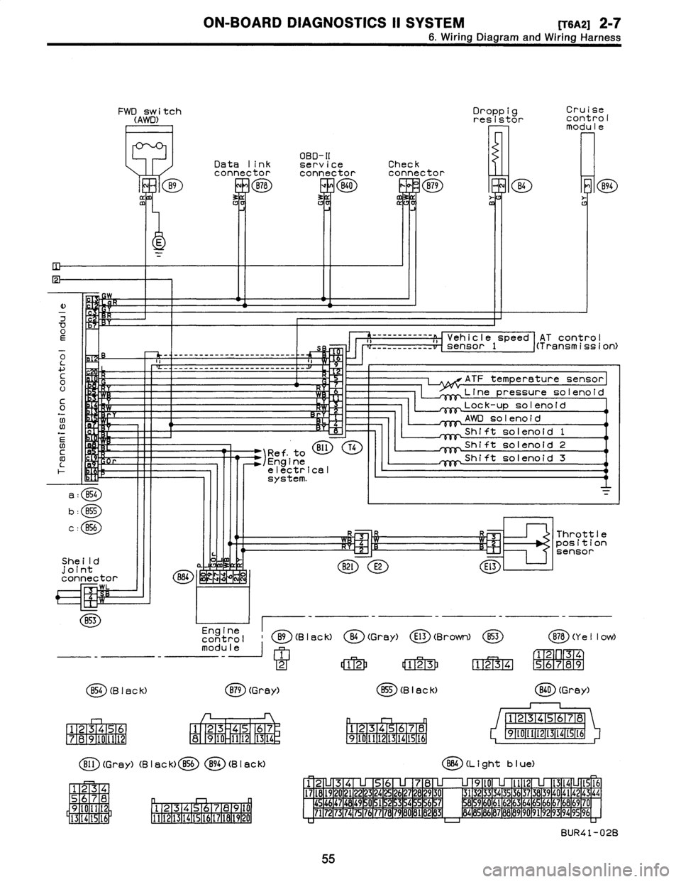
2-7
6
.
Wiring
Diagram
and
Wiring
Harness
FWD
switch
(AWD)
B9
ffl
Droppig
Cruise
resistor
cont
rol
modu
le
OBD-II
Data
link
serviceCheck
connectorconnectorconnector
B78
ERB40
0
B79
m
B4
E
K
E
)
w
7
OEs
o
-
-
-
------------------
-
------
-
-
L
a
....
c
H
0
U
It
C
Y
0
.N
;W
Rr
06
N
BI1
T41
Ref
.
to
/Engine
electrical
system
.
a
:
B54
b
:
B55
c
:
856
She
ild
joint
connector
884
~
WK
LZIM
WL
B53
Engine
control
B9(B
I
ac
k)
module
1
2
854
(B
I
ac
k)
B79
(Grey)
1
23456
1
23
45
67
7
1
8
1
9101112
8
910
1112
1
13
1
14
r,
Bll
(Grey)
(B
I
ac
k)
B56894
(B
I
aCk)
34
S
78
D
q
Oil
2
9
Pl
.
12131415,91617
la19
110
I
5
16
1
3
14
1111121131141151161171161191201
AT
contro
I
------------
a
,,
Vehicle
speed
i(Transmission)
___
_____
__
__
sensor
1
ATF
temperature
sensor
Line
pressuresolenoid
Lock-up
solenoid
AWD
solenoid
Shift
solenoid
1
Shift
solenoid
2
Shift
solenoid
3
R3
Throttle
~-Cz'1
R~l
position
sensor
B2l
E2
El3
O
(Gray)
E13
(Brown)
853
B78
(Y
e
II
ow)
12
123
1234
56789
B55
(B
I
ack)
(
ED
(Grey)
12345678
12345678
9~011t213141St6
91111213141516
864
(L
i
ght
b
I
ue)
12
345678
9l0
lll21314
1516
I7l8l9
20
2122
23
24
2627282930
3132
3334
35
3637383940
4142
43
44
454647
1
48
1
49
~
0
1
51
2
15
3
15
4
~
5
1
56
15
7
8596061626364656667686970
7172
73
1
74
1
75
1
76
1
77
78
1
79
1
60
1
81
B
1
132
1
83d
8485
86
87888990
9192
93
94
9596
BUR41-02B
55
Page 67 of 2890
2-7
[TSB21
ON-BOARD
DIAGNOSTICS
11
SYSTEM
6
.
Wiring
Diagram
and
Wiring
Harness
B
:
ELECTRICAL
WIRING
HARNESS
AND
GROUND
POINT
2
.
BULKHEAD
WIRING
HARNESS
AND
GROUND
POINT
(IN
ENGINE
ROOM)
B6M0587A
56
Page 86 of 2890

ON-BOARD
DIAGNOSTICS
11
SYSTEM
[T11aoj
2-7
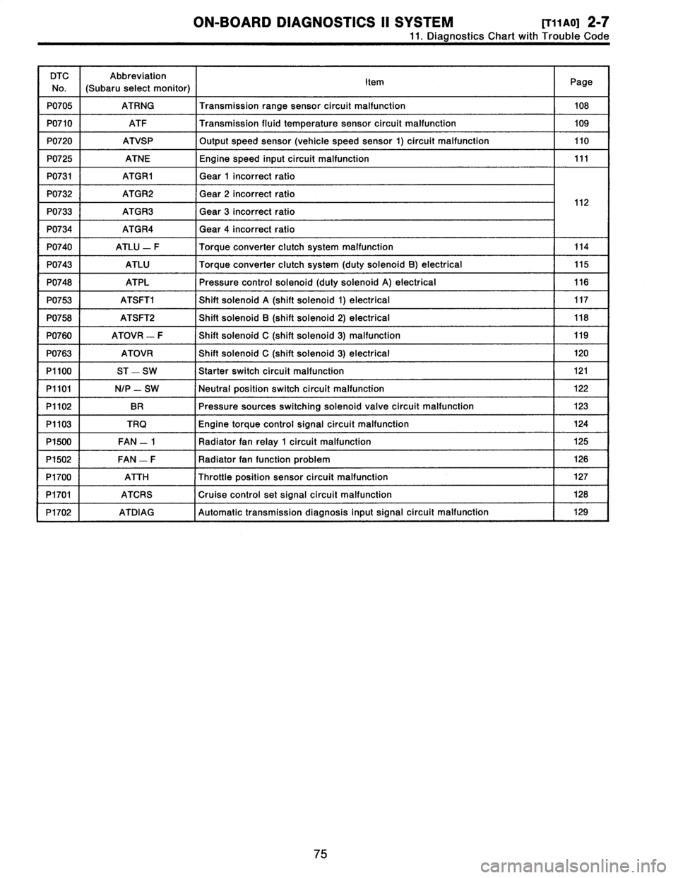
11
.
Diagnostics
Chart
with
Trouble
Code
DTC
No
.
Abbreviation
(Subaru
select
monitor)
Item
Page
P0705
ATRNG
Transmissionrange
sensor
circuit
malfunction
108
P0710
ATF
Transmission
fluid
temperature
sensor
circuit
malfunction
109
P0720
ATVSP
Output
speed
sensor
(vehicle
speed
sensor
1)
circuit
malfunction
110
P0725
ATNE
Engine
speed
input
circuit
malfunction
111
P0731
ATGR1
Gear
1
incorrect
ratio
P0732
ATGR2
Gear
2
incorrect
ratio
1
2
P0733
ATGR3
Gear
3
incorrect
ratio
1
P0734
ATGR4
Gear
4
incorrect
ratio
P0740
ATLU
-
F
Torque
converter
clutch
system
malfunction
114
P0743
ATLU
Torque
converter
clutch
system
(duty
solenoid
B)
electrical
115
P0748
ATPL
Pressure
control
solenoid
(duty
solenoid
A)
electrical
116
P0753
ATSFTi
Shift
solenoid
A
(shift
solenoid
1)
electrical
117
P0758
ATSFT2
Shift
solenoid
B
(shift
solenoid
2)
electrical
118
P0760
ATOVR
-
F
Shift
solenoid
C
(shift
solenoid
3)
malfunction
119
P0763
ATOVR
Shift
solenoid
C
(shift
solenoid
3)
electrical
120
P1100
ST
-
SW
Starter
switch
circuit
malfunction
121
P1101
N/P
-
SW
Neutral
position
switch
circuit
malfunction
122
P1102
BR
Pressure
sources
switching
solenoid
valve
circuit
malfunction
123
P1103
TRQ
Engine
torque
control
signal
circuit
malfunction
124
P1500
FAN
-
1
Radiator
fan
relay
1
circuit
malfunction
125
P1502
FAN
-
F
Radiator
fan
function
problem
126
P1700
ATTH
Throttle
position
sensor
circuit
malfunction
127
P1701
ATCRS
Cruise
control
set
signal
circuit
malfunction
128
P1702
ATDIAG
Automatic
transmission
diagnosis
inputsignal
circuit
malfunction
I
129
75
Page 181 of 2890
![SUBARU LEGACY 1996 Service Repair Manual
WIRING
DIAGRAM
[D605]
6-3
6
.
Wiring
Diagram
FWD
switch
(AWD)
B9
Data
link
connector
B78
OBD-11
service
connector
840
Droppig
Cruise
resistorcont
rol
modu
le
Check
connector
nP
B79
~
B4
~
B SUBARU LEGACY 1996 Service Repair Manual
WIRING
DIAGRAM
[D605]
6-3
6
.
Wiring
Diagram
FWD
switch
(AWD)
B9
Data
link
connector
B78
OBD-11
service
connector
840
Droppig
Cruise
resistorcont
rol
modu
le
Check
connector
nP
B79
~
B4
~
B](/manual-img/17/57433/w960_57433-180.png)
WIRING
DIAGRAM
[D605]
6-3
6
.
Wiring
Diagram
FWD
switch
(AWD)
B9
Data
link
connector
B78
OBD-11
service
connector
840
Droppig
Cruise
resistorcont
rol
modu
le
Check
connector
nP
B79
~
B4
~
B94
0E
o
L
-
-
-
------------------------
-
4
-~
C
-
-------------'---------_
_1'
H
0
U
c0
-
,
F
LO
N
B11
T4
1Ref
.
to
/Engine
F-
r
electrical
system
.
AT
contro
l
--'-'-"----
�
Veh
i
c
l
e
speed
i(Transmission)
___
.---------
-
--
sensor
1
ATF
temperature
sensor
Linepressuresolenoid
Lock-up
solenoid
AWD
solenoid
Shift
solenoid
1
Shift
solenoid
2
Shift
solenoid
3
a
:
B54
b
:
855
c
:
BSb
R
R
3
Throttleposition
She!
I
d
point
n,
821
E2
sensor
El3
connector
B84
B53
~-
--
-
-
contro
II
89
(BI
ac
k)
1
O
(Gray)
E13
(Brown)
B53B78
(Ye
II
Ow)
m
od
ule
1
~
F172-1
3
4
2
12
123
1234
56789
B54
(B
I
ac
k)
B79
(Grey)
B55
(B
I
ac
k)
B40
(Gray)
123456
789101112
1
23
4
67
8
910
1112
11
13
1
14
r,
1
1
1
2
1
3
1
4
1
5
161
7
1
8
1
910111213141516
12345678
910111213141516
(BD
(Gray)
(B
I
ack)
856894
(B
I
ack)
884
(L
i
ght
b
I
ue)
12
34
56
78
9l0
lll2
1314
1516
11181920212223242526272829303132333435363738394041424344
1
2
J3141
56789
10
4546474849
051
1
52
1
53
1
54
1
5
515
6
1
57'
58
4
60
6162
6364656667b8
b970
13142116
I1
1213141516171814
20
7172
73747576
7178
79
80
182
3
8586B7888990
9192
93
949596
BUR41-02B
11
Page 182 of 2890
6-3
[Dso131
WIRING
DIAGRAM
6
.
Wiring
Diagram
Combination
meter
Tachometer
i10
:a
-
110
OD
:
b
Malfunction
i14
I:
c
indicator
~}g
lamp
Speedometer
circuit
ill
Main
relay
o
B47
Twisted
wire
0
B46
E
Fuel
pump
relay
13
.
ENGINE
ELECTRICAL
SYSTEM
To
Power
Supply
Routing
FB-20
~
MB-3
~
FB-4
~
ST
FB-22
Check
FUSENa
15
SBF-2
FUSE
Na
l6IGSW
FUSE
W
15
connector
a
v
B79
,~l,,I
F45
u
B62(2
837
i3
B3B
S
.
M
.
J
.
[Referto
foldout
page
.]
R58R57Rt5
Fuel
M
Y
pump
E
Inhibitor
switch
Bl2
B97817
RI
Vehicle
speed
sensor
2
B17
(B
I
ac
k)
i
tl
B46
(Green)
R15
(B
I
ac
k)
R58
12
1
2
123
12
12334
3456
456
(
2D
(Light
gray)
110
i
l2
(L
I
ght
gray)
1
1
1
2
1
3
1
4
1
5
1
6
M78
9
1
10
1
11
1
12
1
D
1
1234567891011113141516
rnrnmvo~
v
.»ov
.0m
.OMPPmM
.Oh
l~
Enginecontro
I
B84
module
B47
(Brown)
(g
)(Gray)
1
2
1
23
4
31
45
67
85
1
69
1
16N1
1
12
1
-
(
ED
B79
(Gray)
1
23
4567
89
1
10
1112
1314
t2(3
(B
rown)
234789
12345
678910
l
'
1
11
1
1
2l3l4151617181920~~
lll2(31415t6L71819202122
BUR10-02A
12