Page 2707 of 2890
 Connect select monitor.
2) Start the engine and turn cruise control main switch to
ON.
3) Set select monitor in“FB0”mode.
4) Drive vehicle at least 40 km/h")
2. CRUISE CANCEL CONDITIONS DIAGNOSIS
1) Connect select monitor.
2) Start the engine and turn cruise control main switch to
ON.
3) Set select monitor in“FB0”mode.
4) Drive vehicle at least 40 km/h (25 MPH) with cruise
speed set.
5) If cruise speed is canceled itself (without doing any
cancel operations), a trouble code will appear on select
monitor display.
CAUTION:
�A trouble code will also appear when cruise cancel
is effected by driver. Do not confuse.
�Have a co-worker ride in vehicle to assist in diagno-
sis during driving.
NOTE:
Trouble code will be cleared by turning ignition switch or
cruise control main switch to OFF.
3. REAL-TIME DIAGNOSIS
1) Connect select monitor.
2) Turn ignition switch and cruise control main switch to
ON.
3) Set select monitor in“FA 0”mode.
4) Ensure that normal indication is displayed when con-
trols are operated as indicated below:
�When SET/COAST switch is pressed.
�When RESUME/ACCEL switch is pressed.
�When brake pedal is depressed. (Stop and brake switch
turns ON.)
�When clutch pedal is depressed. (MT model)
�When select lever is set to N position. (AT model)
10
6-2BODY ELECTRICAL SYSTEM
6. Diagnostics Chart for On-board Diagnosis System
Page 2721 of 2890
 Start the engine.
4) Shift on the gear position, and keep the vehicle speed
at constant.
5) Measure signal voltage.
Specified voltage (V): 2 V, or more
NOTE:
�If the vehicle speed i")
G2M0931
B6M0287
3) Start the engine.
4) Shift on the gear position, and keep the vehicle speed
at constant.
5) Measure signal voltage.
Specified voltage (V): 2 V, or more
NOTE:
�If the vehicle speed increases, the width of amplitude
(W) decreases.
�If oscilloscope is not available, check input signal
(vehicle speed signal) by using a select monitor. (Refer to
the procedure as described below.)
�Using the select monitor:
(1) Set the vehicle on free roller, or lift-up the vehicle and
support with safety stands.
(2) Turn ignition switch to OFF and set select monitor.
(3) Turn ignition switch to ON.
(4) Turn cruise control main switch to ON.
(5) Set select monitor in“F01”or“F02”mode.
(6) Drive the vehicle at speed greater than 40 km/h (25
MPH).
(7) Check that vehicle speed indication on select moni-
tor and speedometer are equal.
NOTE:
�When there is a disconnection or short circuit in the har-
ness between the meter and the cruise control module, the
indicated value will be 0 to 1.0 km/h (0 to 0.6 MPH).
�In“F01”mode, vehicle speed is indicated in mile per
hour (MPH).
In“F02”mode, vehicle speed is indicated in kilometer per
hour (km/h).
B3M0250
3. PERFORM A CIRCUIT TEST BETWEEN
COMBINATION METER AND CRUISE CONTROL
MODULE.
1) Turn ignition switch to OFF.
2) Remove combination meter.
B6M0194B
3) Disconnect connector from cruise control module.
4) Measure resistance of harness connector between
combination meter and cruise control module.
Connector & terminal / Specified resistance:
(i10) No. 10—(B94) No. 19 / 10Ω, max.
24
6-2BODY ELECTRICAL SYSTEM
8. Diagnostics Chart with Trouble Code
Page 2781 of 2890
13. ENGINE ELECTRICAL SYSTEM
�LHD model
BU10-04A
51
6-3WIRING DIAGRAM
6. Wiring Diagram
Page 2785 of 2890
13. ENGINE ELECTRICAL SYSTEM
�RHD model
BUR10-03A
55
6-3WIRING DIAGRAM
6. Wiring Diagram
Page 2837 of 2890
![SUBARU LEGACY 1996 Service Repair Manual 7. Electrical Unit Location
Electrical unit Refer to;
A.B.S. control module 4-4a [T300]
A.B.S. G sensor (MT) 4-4a [T300]
A/C compressor relay�
7
A/C fuse�11
A/C main fan relay 1�10
A/C main fan relay](/manual-img/17/57433/w960_57433-2836.png "SUBARU LEGACY 1996 Service Repair Manual 7. Electrical Unit Location
Electrical unit Refer to;
A.B.S. control module 4-4a [T300]
A.B.S. G sensor (MT) 4-4a [T300]
A/C compressor relay�
7
A/C fuse�11
A/C main fan relay 1�10
A/C main fan relay")
7. Electrical Unit Location
Electrical unit Refer to;
A.B.S. control module 4-4a [T300]
A.B.S. G sensor (MT) 4-4a [T300]
A/C compressor relay�
7
A/C fuse�11
A/C main fan relay 1�10
A/C main fan relay 2�8
A/C pressure switch�2
A/C sub fan relay 2�9
ATF temperature sensor 2-7 [T2B1]
Blower motor resistor�
26
Blower relay�13
Camshaft position sensor 2-7 [T2A2]
Check connector�
25
Clutch switch (MT) 6-2 [T300]
Crankshaft position sensor 2-7 [T2A2]
Cruise control module 6-2 [T300]
Cruise control pump 6-2 [T300]
Data link connector (for OBD-II G.S.T.) 2-7 [T2A1]
Data link connector (for S.S.M.) 2-7 [T2A1]
Diagnosis connector 4-4a [T300]
Diagnosis terminal (Ground) 4-4a [T300]
Door lock timer�
27
Engine control module 2-7 [T2A1]
Engine coolant temperature sensor 2-7 [T2A2]
Engine hood switch (Security) 6-2 [K6A0]
Evaporator thermoswitch�
29
F/B�15
FRESH/RECIRC actuator�28
Fuel pump relay 2-7 [T2A3]
Fuel gauge module�
31
Fuel gauge sub module (AWD)�32
FWD switch (AT)�1
Headlight alarm relay (Security) 6-2 [K6A0]
Headlight relay LH�
5
Headlight relay RH�6
Horn relay�14
Electrical unit Refer to;
Hydraulic unit (A.B.S.) 4-4a [T300]
Ignition coil 2-7 [T2A3]
Ignitor 2-7 [T2A3]
Idle air control solenoid valve 2-7 [T2A3]
Illumination control module�
21
Inhibitor switch 6-2 [T300]
Knock sensor 2-7 [T2A2]
Main fan relay�
19
Main relay 2-7 [T2A3]
Mass air flow sensor 2-7 [T2A2]
Mode actuator�
12
M/B�4
Oil pressure switch�3
Oxygen sensor 2-7 [T2A2]
Pedal stroke sensor (T.C.S.) 4-4b [T300]
Power window and sunroof relay�
24
Power window circuit breaker�23
Purge control solenoid valve 2-7 [T2A3]
Rear defogger relay�
17
Seat belt timer�20
Security control module 6-2 [K6A0]
Shift lock control module�
22
Starter interrupt relay (Security) 6-2 [K6A0]
Stop & brake switch (With cruise con-
trol)6-2 [T300]
Sunroof control module�
30
Tail and illumination relay�18
T.C.S. control module 4-4b [T300]
T.C.S. motor relay 4-4b [T300]
T.C.S. valve relay 4-4b [T300]
Throttle position sensor 2-7 [T2A2]
Test mode connector 2-7 [T2A1]
Transmission control module 2-7 [T2B1]
Turn & hazard module�
16
Vehicle speed sensor 1 2-7 [T2B1]
Vehicle speed sensor 2 2-7 [T2B1]
107
6-3WIRING DIAGRAM
7. Electrical Unit Location
Page 2838 of 2890
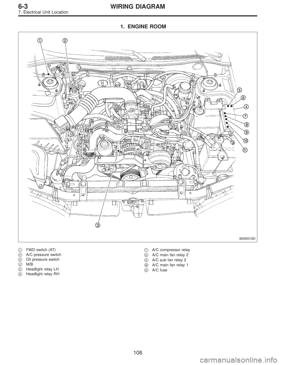
1. ENGINE ROOM
B2M0018D
�1FWD switch (AT)
�
2A/C pressure switch
�
3Oil pressure switch
�
4M/B
�
5Headlight relay LH
�
6Headlight relay RH�
7A/C compressor relay
�
8A/C main fan relay 2
�
9A/C sub fan relay 2
�
10A/C main fan relay 1
�
11A/C fuse
108
6-3WIRING DIAGRAM
7. Electrical Unit Location
Page 2843 of 2890
8. Electrical Wiring Harness and
Ground Point
B6M0267A
�1Front wiring harness
�
2Engine wiring harness
�
3Room light cord
�
4Bulkhead wiring harness
�
5Instrument panel wiring harness
�
6Front door cord RH
�
7Rear door cord RH
�
8Rear wiring harness
�
9Trunk lid cord (Sedan)�
10Rear defogger ground cord (Sedan)
�
11Fuel tank cord
�
12Rear door cord LH
�
13Front door cord LH
�
14Sunroof cord
�
15Floor wiring harness
�
16Transmission cord
�
17Rear gate cord (Wagon)
�
18Rear oxygen sensor cord
11 3
6-3WIRING DIAGRAM
8. Electrical Wiring Harness and Ground Point
Page 2848 of 2890
2. BULKHEAD WIRING HARNESS AND GROUND POINT (IN ENGINE ROOM)
�LHD model
EPA0097
11 8
6-3WIRING DIAGRAM
8. Electrical Wiring Harness and Ground Point