Page 867 of 2890

C: LINE PRESSURE TEST
1. GENERAL
If the clutch or the brake band shows a sign of slippage or
shifting sensation is not correct, the line pressure should be
checked.
�Excessive shocks during upshifting or shifting takes
place at a higher point than under normal circumstances,
may be due to the line pressure being too high.
�Slippage or inability to operate the vehicle may, in most
cases, be due to loss of oil pressure for the operation of
the clutch, brake band or control valve.
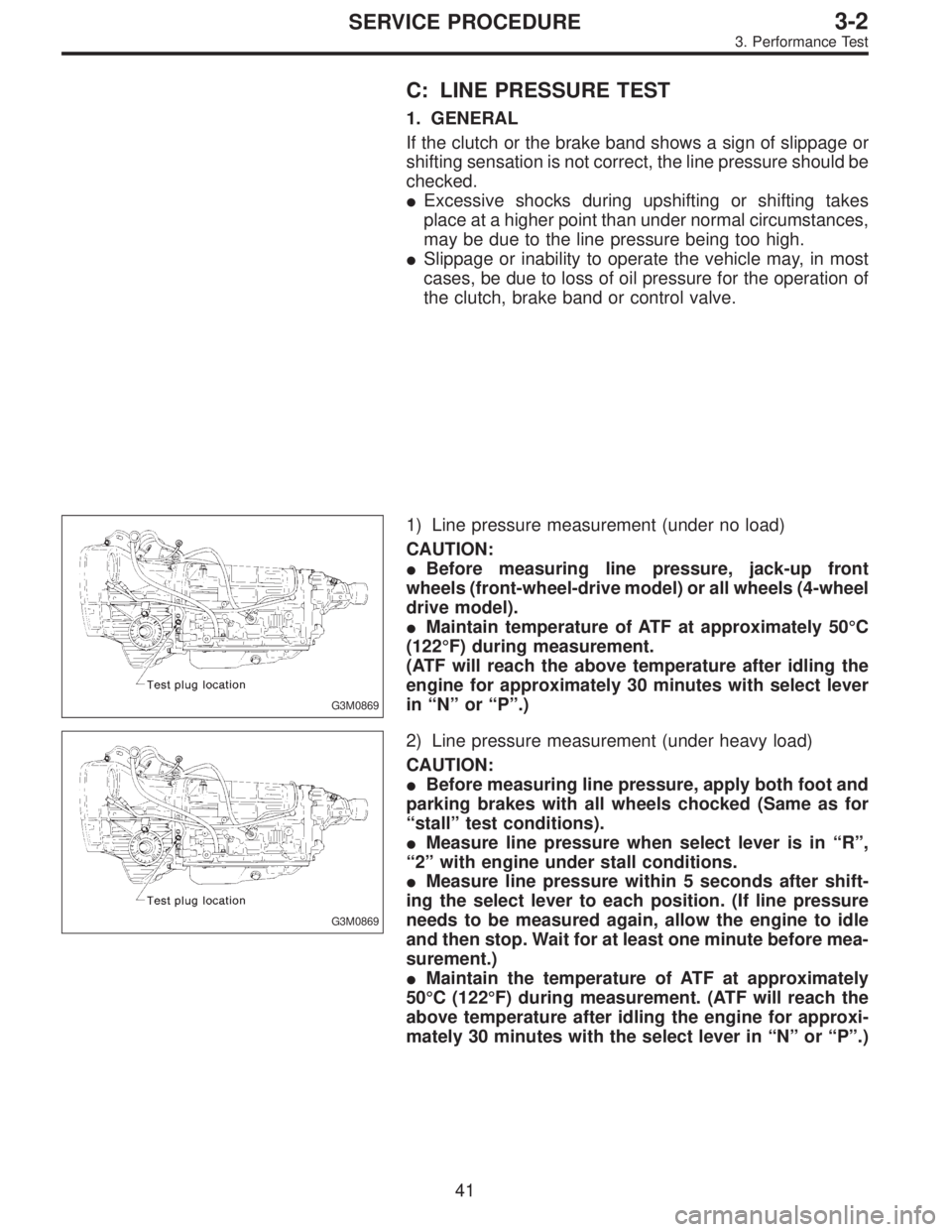
G3M0869
1) Line pressure measurement (under no load)
CAUTION:
�Before measuring line pressure, jack-up front
wheels (front-wheel-drive model) or all wheels (4-wheel
drive model).
�Maintain temperature of ATF at approximately 50°C
(122°F) during measurement.
(ATF will reach the above temperature after idling the
engine for approximately 30 minutes with select lever
in“N”or“P”.)
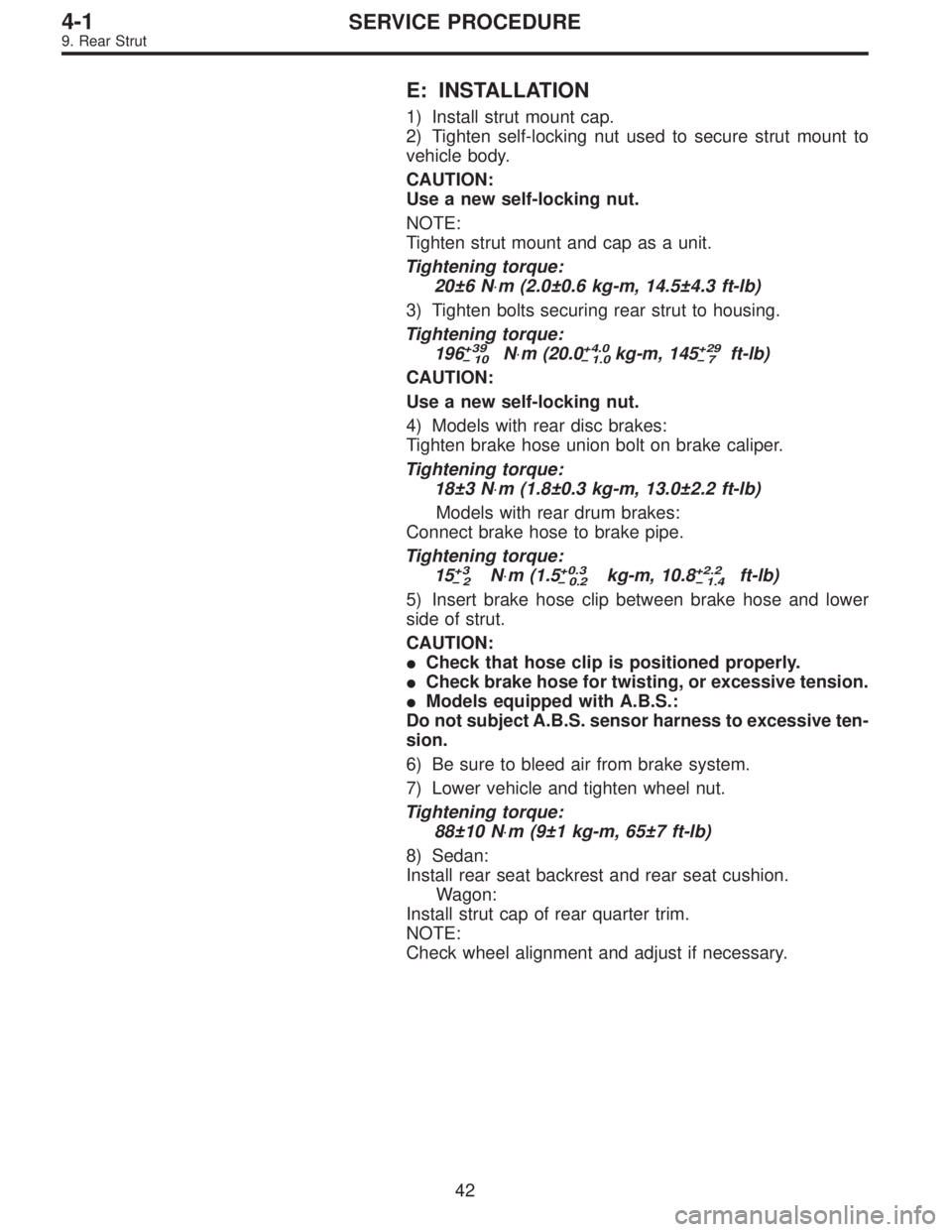
G3M0869
2) Line pressure measurement (under heavy load)
CAUTION:
�Before measuring line pressure, apply both foot and
parking brakes with all wheels chocked (Same as for
“stall”test conditions).
�Measure line pressure when select lever is in“R”,
“2”with engine under stall conditions.
�Measure line pressure within 5 seconds after shift-
ing the select lever to each position. (If line pressure
needs to be measured again, allow the engine to idle
and then stop. Wait for at least one minute before mea-
surement.)
�Maintain the temperature of ATF at approximately
50°C (122°F) during measurement. (ATF will reach the
above temperature after idling the engine for approxi-
mately 30 minutes with the select lever in“N”or“P”.)
41
3-2SERVICE PROCEDURE
3. Performance Test
Page 1042 of 2890
G4M0538
7) Models equipped with rear disc brakes:
Remove union bolt from brake caliper.
8) Models equipped with rear drum brakes:
Disconnect brake hose from brake pipe from strut, and
disconnect brake pipe from dram brake.
G4M0539
9) Remove bolts which secure rear strut to housing.
10) Remove nuts securing strut mount to body.
11) Remove strut mount cap.
B: DISASSEMBLY
For disassembly of rear strut, refer to procedures outlined
under front strut as a guide.
C: INSPECTION
Refer to Front Strut 4-1 [W4C0] as a guide for inspection
procedures.
G4M0540
D: ASSEMBLY
Refer to Front Strut 4-1 [W4D0] as a guide for assembly
procedures.
CAUTION:
�Install rear strut with “FWD” or “4WD” mark on strut
mount facing outside of vehicle body.
�Insert the protrusion of lower rubber seat into the
strut spring seat hole.
41
4-1SERVICE PROCEDURE
9. Rear Strut
Page 1043 of 2890

E: INSTALLATION
1) Install strut mount cap.
2) Tighten self-locking nut used to secure strut mount to
vehicle body.
CAUTION:
Use a new self-locking nut.
NOTE:
Tighten strut mount and cap as a unit.
Tightening torque:
20±6 N⋅m (2.0±0.6 kg-m, 14.5±4.3 ft-lb)
3) Tighten bolts securing rear strut to housing.
Tightening torque:
196
+39
�10N⋅m (20.0+4.0
�1.0kg-m, 145+29
�7ft-lb)
CAUTION:
Use a new self-locking nut.
4) Models with rear disc brakes:
Tighten brake hose union bolt on brake caliper.
Tightening torque:
18±3 N⋅m (1.8±0.3 kg-m, 13.0±2.2 ft-lb)
Models with rear drum brakes:
Connect brake hose to brake pipe.
Tightening torque:
15
+3
�2N⋅m (1.5+0.3
�0.2kg-m, 10.8+2.2
�1.4ft-lb)
5) Insert brake hose clip between brake hose and lower
side of strut.
CAUTION:
�Check that hose clip is positioned properly.
�Check brake hose for twisting, or excessive tension.
�Models equipped with A.B.S.:
Do not subject A.B.S. sensor harness to excessive ten-
sion.
6) Be sure to bleed air from brake system.
7) Lower vehicle and tighten wheel nut.
Tightening torque:
88±10 N⋅m (9±1 kg-m, 65±7 ft-lb)
8) Sedan:
Install rear seat backrest and rear seat cushion.
Wagon:
Install strut cap of rear quarter trim.
NOTE:
Check wheel alignment and adjust if necessary.
42
4-1SERVICE PROCEDURE
9. Rear Strut
Page 1071 of 2890

Drum brake: Perform steps 9) through 11).
9) Clean brake pipe connection. Using a flare-nut wrench,
connect brake pipe to wheel cylinder.
10) Connect parking brake cable to lever.
11) Install brake drum on rear housing assembly.
12) Bleed air from brake system.
13) Adjust parking brake lever stroke by turning adjuster.
14) Move brake lever back to apply brakes. While
depressing brake pedal, tighten axle nut using a socket
wrench. Lock axle nut after tightening.
Tightening torque:
186±20 N⋅m (19±2 kg-m, 137±14 ft-lb)
CAUTION:
�Use a new axle nut.
�Always tighten axle nut before installing wheel on
vehicle. If wheel is installed and comes in contact with
ground when axle nut is loose, wheel bearings may be
damaged.
�Be sure to tighten axle nut to specified torque. Do
not overtighten it as this may damage wheel bearing.
15) Install wheel and tighten wheel nuts to specified
torque.
Tightening torque:
88±10 N⋅m (9±1 kg-m, 65±7 ft-lb)
3. Rear Axle (FWD Model)
A: REMOVAL
1) Disconnect ground cable from battery.
2) Jack-up vehicle, and remove rear wheel cap and
wheels.
CAUTION:
Be sure to loosen and retighten axle nut after remov-
ing wheel from vehicle. Failure to follow this rule may
damage wheel bearings.
3) Pry hub cap off with a screwdriver placed between it
and hub.
4) Unlock axle nut.
5) Remove axle nut using a socket wrench. Remove
washer.
CAUTION:
Do not re-use old axle nut. Replace with a new one.
NOTE:
Temporarily tighten axle nut to hold hub in place.
23
4-2SERVICE PROCEDURE
2. Rear Axle (AWD Model) - 3. Rear Axle (FWD Model)
Page 1072 of 2890

Drum brake: Perform steps 9) through 11).
9) Clean brake pipe connection. Using a flare-nut wrench,
connect brake pipe to wheel cylinder.
10) Connect parking brake cable to lever.
11) Install brake drum on rear housing assembly.
12) Bleed air from brake system.
13) Adjust parking brake lever stroke by turning adjuster.
14) Move brake lever back to apply brakes. While
depressing brake pedal, tighten axle nut using a socket
wrench. Lock axle nut after tightening.
Tightening torque:
186±20 N⋅m (19±2 kg-m, 137±14 ft-lb)
CAUTION:
�Use a new axle nut.
�Always tighten axle nut before installing wheel on
vehicle. If wheel is installed and comes in contact with
ground when axle nut is loose, wheel bearings may be
damaged.
�Be sure to tighten axle nut to specified torque. Do
not overtighten it as this may damage wheel bearing.
15) Install wheel and tighten wheel nuts to specified
torque.
Tightening torque:
88±10 N⋅m (9±1 kg-m, 65±7 ft-lb)
3. Rear Axle (FWD Model)
A: REMOVAL
1) Disconnect ground cable from battery.
2) Jack-up vehicle, and remove rear wheel cap and
wheels.
CAUTION:
Be sure to loosen and retighten axle nut after remov-
ing wheel from vehicle. Failure to follow this rule may
damage wheel bearings.
3) Pry hub cap off with a screwdriver placed between it
and hub.
4) Unlock axle nut.
5) Remove axle nut using a socket wrench. Remove
washer.
CAUTION:
Do not re-use old axle nut. Replace with a new one.
NOTE:
Temporarily tighten axle nut to hold hub in place.
23
4-2SERVICE PROCEDURE
2. Rear Axle (AWD Model) - 3. Rear Axle (FWD Model)
Page 1207 of 2890
1. Brakes
A: SPECIFICATIONS
1. MODELS WITH ABS OR ABS/TCS
Model Sedan Wagon
Engine (cc) 2200 2200
Driving system FWD AWD FWD AWD
L+ L+ LS L+ L+ OUTBACK LS
Front
brakeType Disc (Floating type, ventilated)
Effective disc diameter
mm (in)210 (8.27)
Disc thickness x Outer
diameter
mm (in)24 x 260 (0.94 x 10.24)
Effective cylinder
diameter
mm (in)57.2 (2.252)
Pad dimensions
(length x width x
thickness)
mm (in)112.4 x 44.3 x 11.0 (4.43 x 1.744 x 0.433)
Clearance adjustment Automatic adjustment
Rear
brakeType Disc (Floating type)
Effective disc diameter
mm (in)230 (9.06)
Disc thickness x Outer
diameter
mm (in)10 x 266 (0.39 x 10.47)
Effective cylinder
diameter
mm (in)34.9 (1.374) 38.1 (1.500)
Pad dimensions
(length x width x
thickness)
mm (in)92.4 x 33.7 x 10.0 (3.638 x 1.327 x 0.394)
Clearance adjustment Automatic adjustment
2
4-4SPECIFICATIONS AND SERVICE DATA
1. Brakes
Page 1208 of 2890
Model 4 Door Sedan Wagon
Engine (cc) 2200 2200
Driving system FWD AWD FWD AWD
L+ L+ LS L+ L+ OUTBACK LS
Hill holder��——��—
Parking
brakeType Mechanical on rear brakes, drum in disc
Effective drum diameter
mm (in)170 (6.69)
Lining dimensions
(length x width x
thickness)
mm (in)162.6 x 30.0 x 3.2 (6.40 x 1.181 x 0.126)
Clearance adjustment Manual adjustment
Master
cylinderType Tandem
Effective diameter
mm (in)26.99 (1-1/16)
Reservoir type Sealed type
Brake fluid reservoir
capacity
cm
3(cu in)190 (11.59)
Brake
boosterType Vacuum suspended
Effective diameter
mm (in)205 + 230 (8.07 + 9.06)
Proportioning
valveSplit point
kPa (kg/cm
2, psi)2,942 (30.0, 427)
Reducing ratio 0.3
Brake line Dual circuit system
ABS—OP STD—OP OP STD
ABS/TCS OP—OP—
�: Equipped on manual transmission vehicle. (Except TCS model)
3
4-4SPECIFICATIONS AND SERVICE DATA
1. Brakes
Page 1209 of 2890
2. MODELS WITHOUT ABS OR ABS/TCS
Model Sedan Wagon
Engine (cc) 2200
Driving system FWD AWD FWD AWD
L, L+ L, L+ L, L+ POST BRIGHTON L, L+ OUTBACK
Front
brakeType Disc (Floating type, ventilated)
Effective disc diameter
mm (in)210 (8.27)
Disc thickness x Outer
diameter
mm (in)24 x 260 (0.94 x 10.24)
Effective cylinder
diameter
mm (in)57.2 (2.252)
Pad dimensions
(length x width x
thickness)
mm (in)112.4 x 44.3 x 11.0 (4.43 x 1.744 x 0.433)
Clearance adjustment Automatic adjustment
Rear
brakeType Drum (Leading-Trailing type)
Effective drum diameter
mm (in)228.6 (9)
Effective cylinder
diameter
mm (in)17.4 (0.685) 19.0 (0.748)
Lining dimensions
(length x width x
thickness)
mm (in)218.8 x 35.0 x 4.1 (8.61 x 1.378 x 0.161)
Clearance adjustment Automatic adjustment
4
4-4SPECIFICATIONS AND SERVICE DATA
1. Brakes