Page 1210 of 2890
Model Sedan Wagon
Engine (cc) 2200
Driving system FWD AWD FWD AWD
L+ L+ L+ POST BRIGHTON L+ OUTBACK
Hill holder��—— —�—
Parking
brakeType Mechanical on rear brakes, drum in disc
Effective drum diameter
mm (in)228.6 (9)
Lining dimensions
(length x width x
thickness
mm (in)218.8 x 35.0 x 4.1 (8.61 x 1.378 x 0.161)
Clearance adjustment Automatic adjustment
Master
cylinderType Tandem
Effective diameter
mm (in)23.81 (15/16)
Reservoir type Sealed type
Brake fluid reservoir
capacity
cm
3(cu in)190 (11.59)
Brake
boosterType Vacuum suspended
Effective diameter
mm (in)230 (9.06)
Proportioning
valveSplit point
kPa (kg/cm
2, psi)3,678 (37.5, 533)
Reducing ratio 0.3
Brake line Dual circuit system
�: Equipped on manual transmission vehicle.
5
4-4SPECIFICATIONS AND SERVICE DATA
1. Brakes
Page 1211 of 2890
3. 2500 cc AND OUTBACK (STEP ROOF) MODEL
Model Sedan Wagon
Engine (cc) 2500 2200 2500
Driving system AWD
GT LSi GT LSi OUTBACK* OUTBACK*
Front
brakeType Disc (Floating type, ventilated)
Effective disc diameter
mm (in)228 (8.98)
Disc thickness x Outer
diameter
mm (in)24 x 277 (0.94 x 10.91)
Effective cylinder
diameter
mm (in)42.8 (1.687) x 2
Pad dimensions
(length x width x
thickness)
mm (in)112.3 x 50.0 x 11.0 (4.42 x 1.969 x 0.433)
Clearance adjustment Automatic adjustment
Rear
brakeType Disc (Floating type)
Effective disc diameter
mm (in)230 (9.06)
Disc thickness x Outer
diameter
mm (in)10 x 266 (0.39 x 10.47)
Effective cylinder
diameter
mm (in)38.1 (1.500)
Pad dimensions
(length x width x
thickness)
mm (in)92.4 x 33.7 x 10.0 (3.638 x 1.327 x 0.394)
Clearance adjustment Automatic adjustment
*: Step roof model
6
4-4SPECIFICATIONS AND SERVICE DATA
1. Brakes
Page 1212 of 2890
Model Sedan Wagon
Engine (cc) 2500 2200 2500
Driving system AWD
GT LSi GT LSi OUTBACK* OUTBACK*
Hill holder————STD—
Parking
brakeType Mechanical on rear brakes, drum in disc
Effective drum diameter
mm (in)170 (6.69)
Lining dimensions
(length x width x
thickness)
mm (in)162.6 x 30.0 x 3.2 (6.40 x 1.181 x 0.126)
Clearance adjustment Manual adjustment
Master
cylinderType Tandem
Effective diameter
mm (in)26.99 (1-1/16)
Reservoir type Sealed type
Brake fluid reservoir
capacity
cm
3(cu in)190 (11.59)
Brake
boosterType Vacuum suspended
Effective diameter
mm (in)205 + 230 (8.07 + 9.06)
Propor-
tioning
valveSplit point
kPa (kg/cm
2, psi)3,678 (37.5, 533)
Reducing ratio 0.3
Brake line Dual circuit system
ABSSTD
*: Step roof model
7
4-4SPECIFICATIONS AND SERVICE DATA
1. Brakes
Page 1213 of 2890
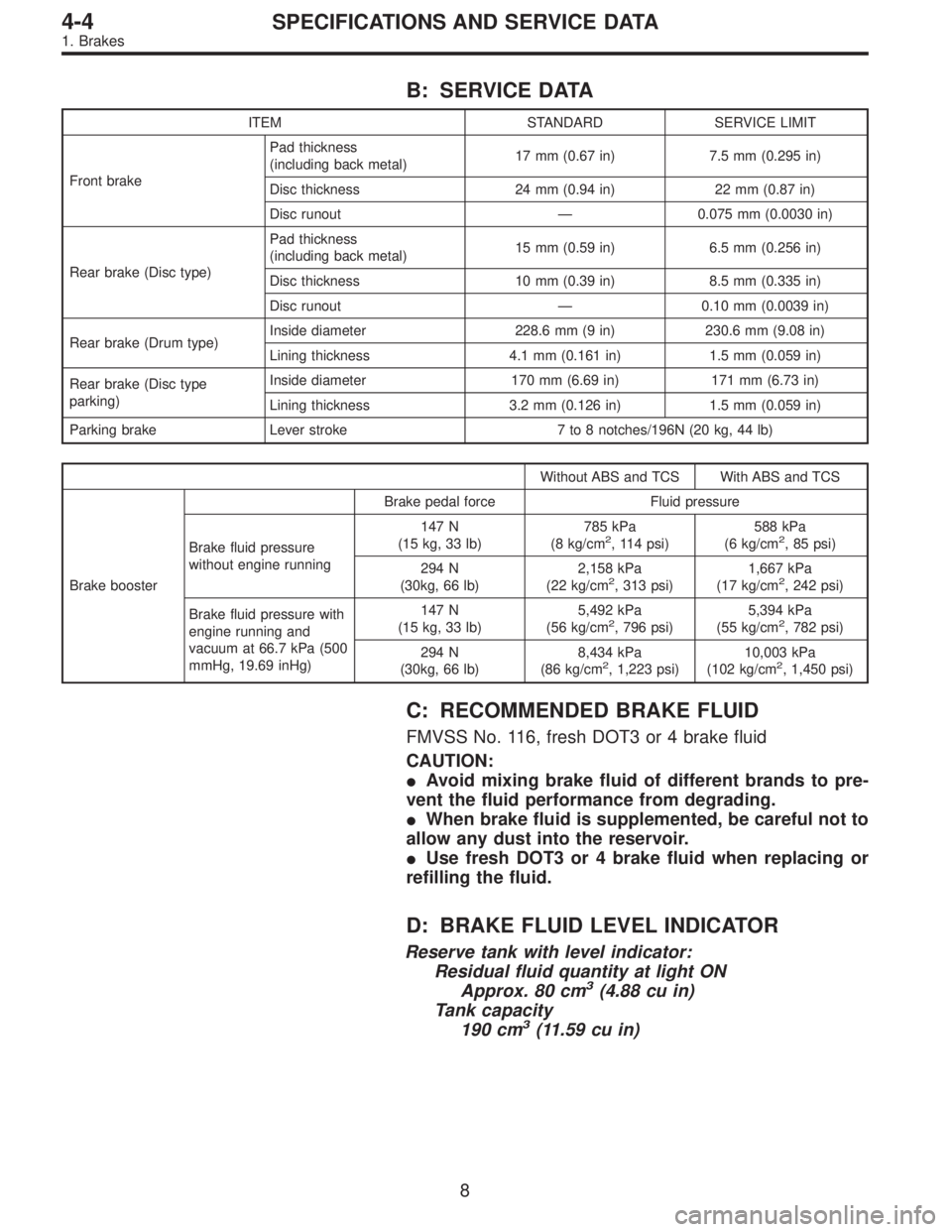
B: SERVICE DATA
ITEM STANDARD SERVICE LIMIT
Front brakePad thickness
(including back metal)17 mm (0.67 in) 7.5 mm (0.295 in)
Disc thickness 24 mm (0.94 in) 22 mm (0.87 in)
Disc runout—0.075 mm (0.0030 in)
Rear brake (Disc type)Pad thickness
(including back metal)15 mm (0.59 in) 6.5 mm (0.256 in)
Disc thickness 10 mm (0.39 in) 8.5 mm (0.335 in)
Disc runout—0.10 mm (0.0039 in)
Rear brake (Drum type)Inside diameter 228.6 mm (9 in) 230.6 mm (9.08 in)
Lining thickness 4.1 mm (0.161 in) 1.5 mm (0.059 in)
Rear brake (Disc type
parking)Inside diameter 170 mm (6.69 in) 171 mm (6.73 in)
Lining thickness 3.2 mm (0.126 in) 1.5 mm (0.059 in)
Parking brake Lever stroke 7 to 8 notches/196N (20 kg, 44 lb)
Without ABS and TCS With ABS and TCS
Brake boosterBrake pedal force Fluid pressure
Brake fluid pressure
without engine running147 N
(15 kg, 33 lb)785 kPa
(8 kg/cm
2, 114 psi)588 kPa
(6 kg/cm2, 85 psi)
294 N
(30kg, 66 lb)2,158 kPa
(22 kg/cm
2, 313 psi)1,667 kPa
(17 kg/cm2, 242 psi)
Brake fluid pressure with
engine running and
vacuum at 66.7 kPa (500
mmHg, 19.69 inHg)147 N
(15 kg, 33 lb)5,492 kPa
(56 kg/cm
2, 796 psi)5,394 kPa
(55 kg/cm2, 782 psi)
294 N
(30kg, 66 lb)8,434 kPa
(86 kg/cm
2, 1,223 psi)10,003 kPa
(102 kg/cm2, 1,450 psi)
C: RECOMMENDED BRAKE FLUID
FMVSS No. 116, fresh DOT3 or 4 brake fluid
CAUTION:
�Avoid mixing brake fluid of different brands to pre-
vent the fluid performance from degrading.
�When brake fluid is supplemented, be careful not to
allow any dust into the reservoir.
�Use fresh DOT3 or 4 brake fluid when replacing or
refilling the fluid.
D: BRAKE FLUID LEVEL INDICATOR
Reserve tank with level indicator:
Residual fluid quantity at light ON
Approx. 80 cm
3(4.88 cu in)
Tank capacity
190 cm
3(11.59 cu in)
8
4-4SPECIFICATIONS AND SERVICE DATA
1. Brakes
Page 1251 of 2890
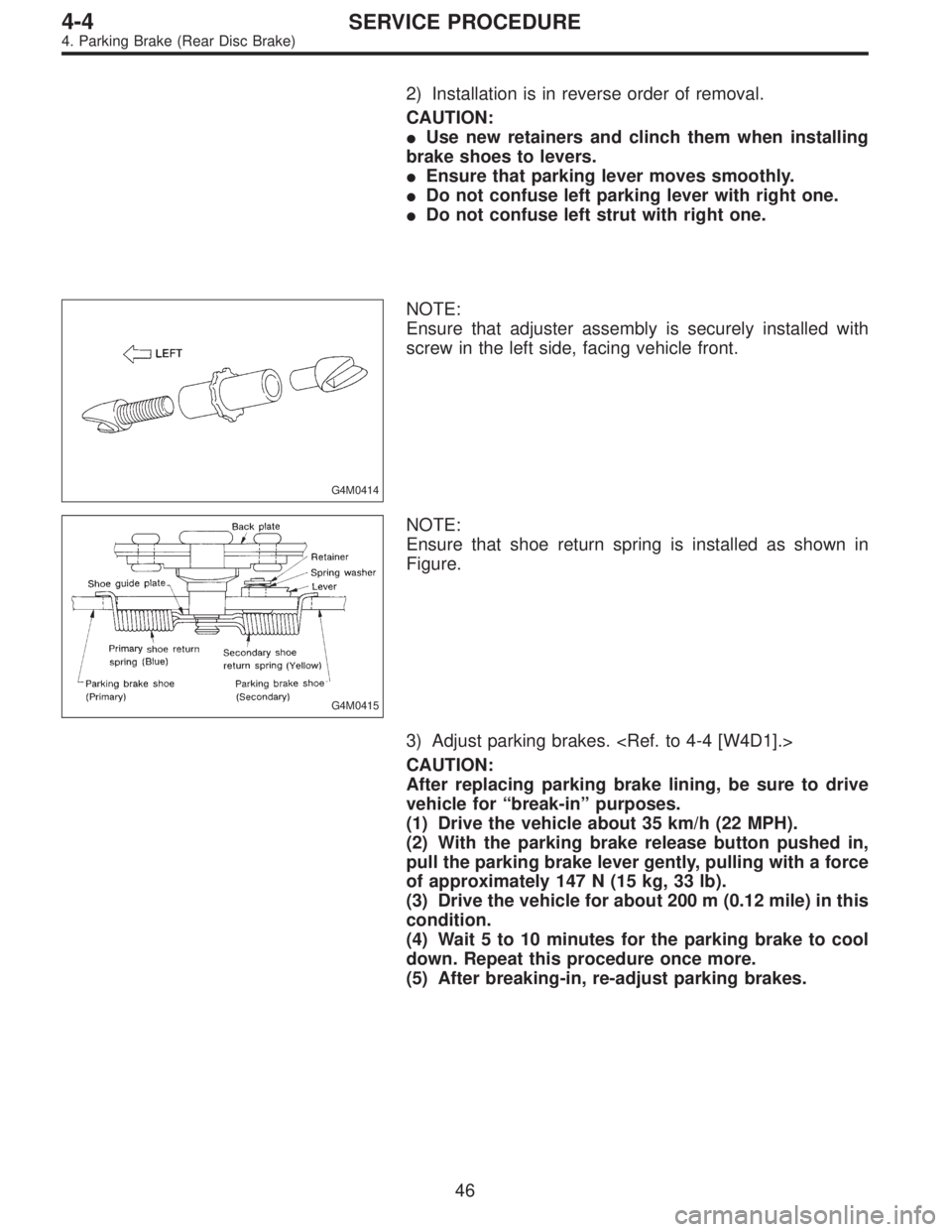
2) Installation is in reverse order of removal.
CAUTION:
�Use new retainers and clinch them when installing
brake shoes to levers.
�Ensure that parking lever moves smoothly.
�Do not confuse left parking lever with right one.
�Do not confuse left strut with right one.
G4M0414
NOTE:
Ensure that adjuster assembly is securely installed with
screw in the left side, facing vehicle front.
G4M0415
NOTE:
Ensure that shoe return spring is installed as shown in
Figure.
3) Adjust parking brakes.
CAUTION:
After replacing parking brake lining, be sure to drive
vehicle for“break-in”purposes.
(1) Drive the vehicle about 35 km/h (22 MPH).
(2) With the parking brake release button pushed in,
pull the parking brake lever gently, pulling with a force
of approximately 147 N (15 kg, 33 lb).
(3) Drive the vehicle for about 200 m (0.12 mile) in this
condition.
(4) Wait 5 to 10 minutes for the parking brake to cool
down. Repeat this procedure once more.
(5) After breaking-in, re-adjust parking brakes.
46
4-4SERVICE PROCEDURE
4. Parking Brake (Rear Disc Brake)
Page 1257 of 2890
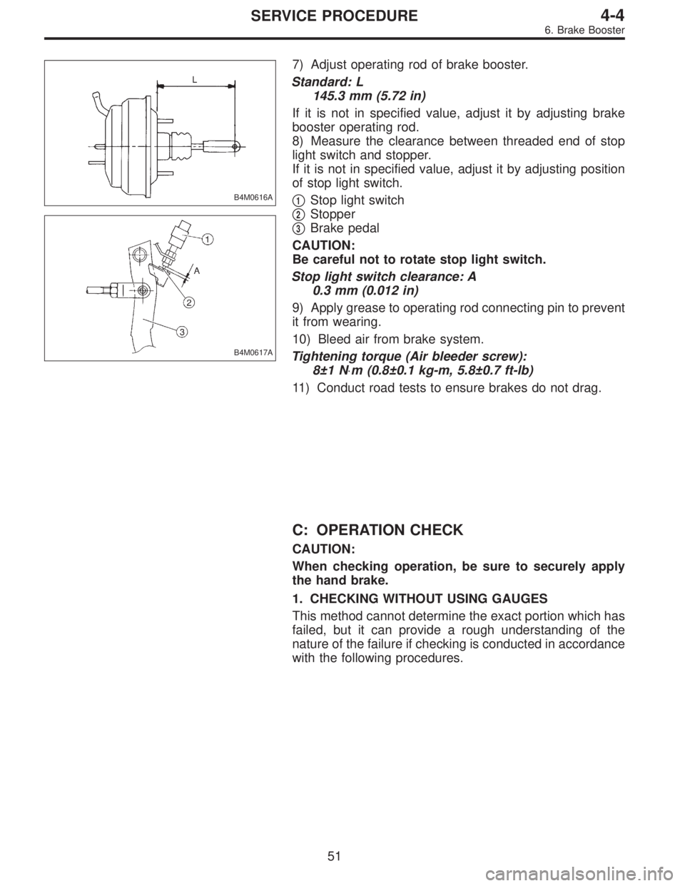
B4M0616A
B4M0617A
7) Adjust operating rod of brake booster.
Standard: L
145.3 mm (5.72 in)
If it is not in specified value, adjust it by adjusting brake
booster operating rod.
8) Measure the clearance between threaded end of stop
light switch and stopper.
If it is not in specified value, adjust it by adjusting position
of stop light switch.
�
1Stop light switch
�
2Stopper
�
3Brake pedal
CAUTION:
Be careful not to rotate stop light switch.
Stop light switch clearance: A
0.3 mm (0.012 in)
9) Apply grease to operating rod connecting pin to prevent
it from wearing.
10) Bleed air from brake system.
Tightening torque (Air bleeder screw):
8±1 N⋅m (0.8±0.1 kg-m, 5.8±0.7 ft-lb)
11) Conduct road tests to ensure brakes do not drag.
C: OPERATION CHECK
CAUTION:
When checking operation, be sure to securely apply
the hand brake.
1. CHECKING WITHOUT USING GAUGES
This method cannot determine the exact portion which has
failed, but it can provide a rough understanding of the
nature of the failure if checking is conducted in accordance
with the following procedures.
51
4-4SERVICE PROCEDURE
6. Brake Booster
Page 1269 of 2890
11. Air Bleeding (Without TCS model)
A: GENERAL RULES FOR EFFECTIVE
BLEEDING
1) Start with the brakes (wheels) connecting to the sec-
ondary chamber of the master cylinder.
2) The time interval between two brake pedal operations
(from the time when the pedal is released to the time when
it is depressed another time) shall be approximately 3 sec-
onds.
3) The air bleeder on each brake shall be released for 1
to 2 seconds.
B: BLEEDING PROCEDURE
CAUTION:
�The FMVSS No. 116, fresh DOT3 or 4 brake fluid
must be used.
�Cover bleeder with waste cloth, when loosening it,
to prevent brake fluid from being splashed over sur-
rounding parts.
�Avoid mixing different brands of brake fluid to pre-
vent degrading the quality of the fluid.
�Be careful not to allow dirt or dust to get into the
reservoir tank.
NOTE:
�During bleeding operation, keep the brake reserve tank
filled with brake fluid to eliminate entry of air.
�Brake pedal operating must be very slow.
�For convenience and safety, it is advisable to have two
man working.
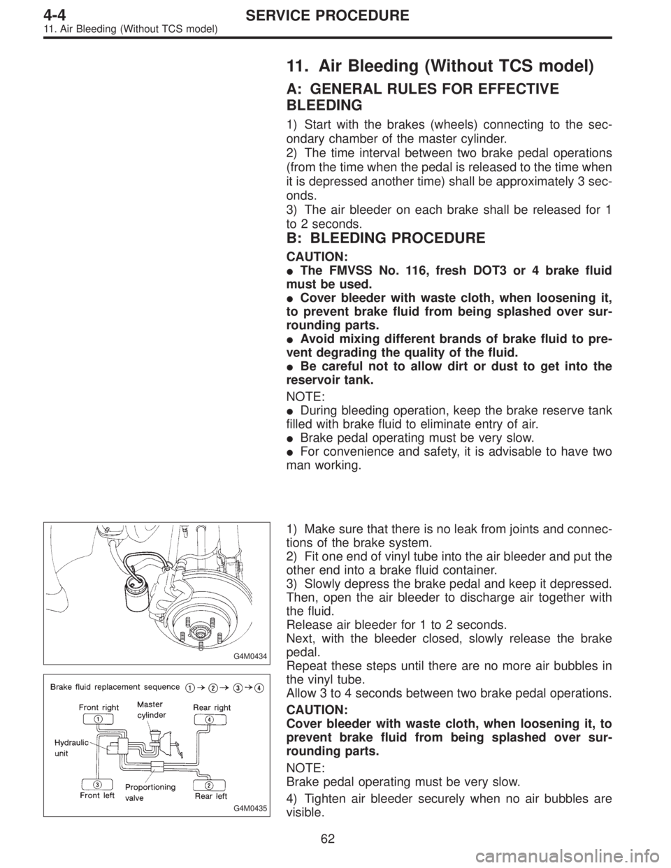
G4M0434
G4M0435
1) Make sure that there is no leak from joints and connec-
tions of the brake system.
2) Fit one end of vinyl tube into the air bleeder and put the
other end into a brake fluid container.
3) Slowly depress the brake pedal and keep it depressed.
Then, open the air bleeder to discharge air together with
the fluid.
Release air bleeder for 1 to 2 seconds.
Next, with the bleeder closed, slowly release the brake
pedal.
Repeat these steps until there are no more air bubbles in
the vinyl tube.
Allow 3 to 4 seconds between two brake pedal operations.
CAUTION:
Cover bleeder with waste cloth, when loosening it, to
prevent brake fluid from being splashed over sur-
rounding parts.
NOTE:
Brake pedal operating must be very slow.
4) Tighten air bleeder securely when no air bubbles are
visible.
62
4-4SERVICE PROCEDURE
11. Air Bleeding (Without TCS model)
Page 1270 of 2890
Air bleeder tightening torque:
8±1 N⋅m (0.8±0.1 kg-m, 5.8±0.7 ft-lb)
5) Perform these steps for the brakes connecting to the
secondary chamber of master cylinder, first, and then for
the ones connecting to primary chamber. With all proce-
dures completed, fully depress the brake pedal and keep
it in that position for approximately 20 seconds to make
sure that there is no leak evident in the entire system.
G4M0436
6) Perform sequence control. (With ABS model)
4-4 [W15C1].>
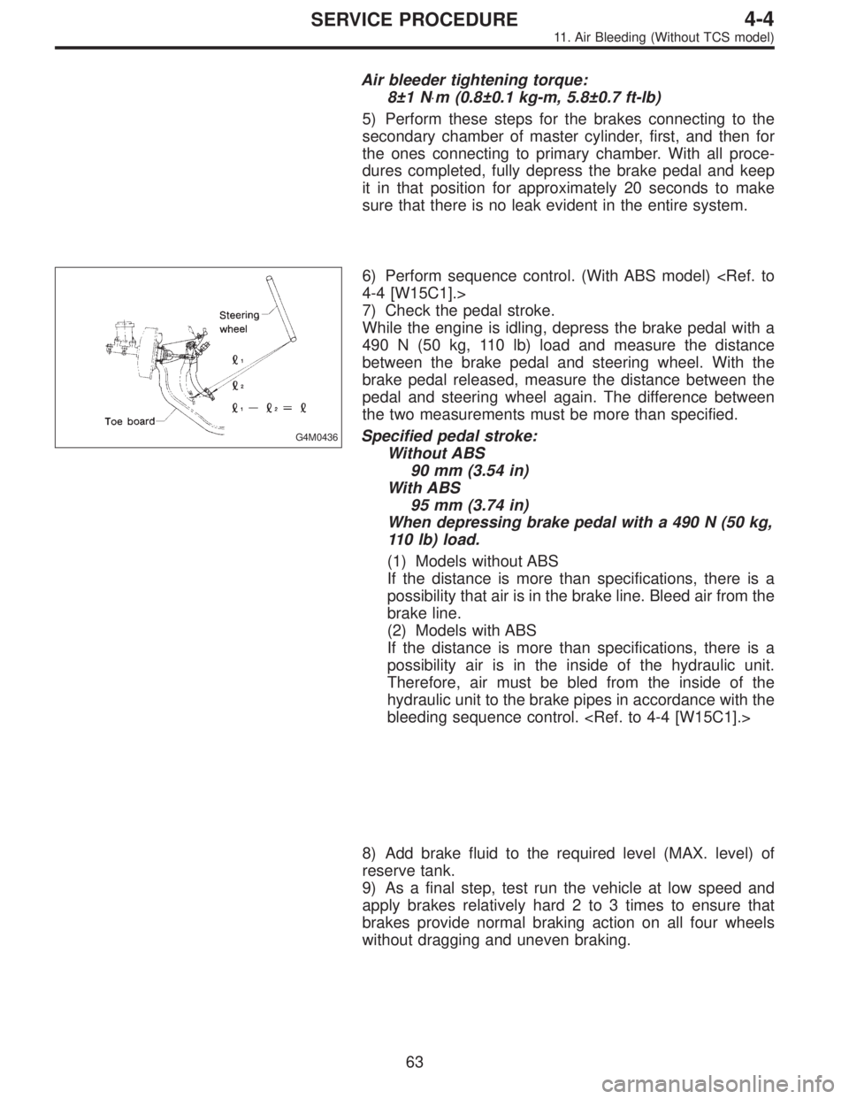
7) Check the pedal stroke.
While the engine is idling, depress the brake pedal with a
490 N (50 kg, 110 lb) load and measure the distance
between the brake pedal and steering wheel. With the
brake pedal released, measure the distance between the
pedal and steering wheel again. The difference between
the two measurements must be more than specified.
Specified pedal stroke:
Without ABS
90 mm (3.54 in)
With ABS
95 mm (3.74 in)
When depressing brake pedal with a 490 N (50 kg,
110 lb) load.
(1) Models without ABS
If the distance is more than specifications, there is a
possibility that air is in the brake line. Bleed air from the
brake line.
(2) Models with ABS
If the distance is more than specifications, there is a
possibility air is in the inside of the hydraulic unit.
Therefore, air must be bled from the inside of the
hydraulic unit to the brake pipes in accordance with the
bleeding sequence control.
8) Add brake fluid to the required level (MAX. level) of
reserve tank.
9) As a final step, test run the vehicle at low speed and
apply brakes relatively hard 2 to 3 times to ensure that
brakes provide normal braking action on all four wheels
without dragging and uneven braking.
63
4-4SERVICE PROCEDURE
11. Air Bleeding (Without TCS model)