Page 1272 of 2890
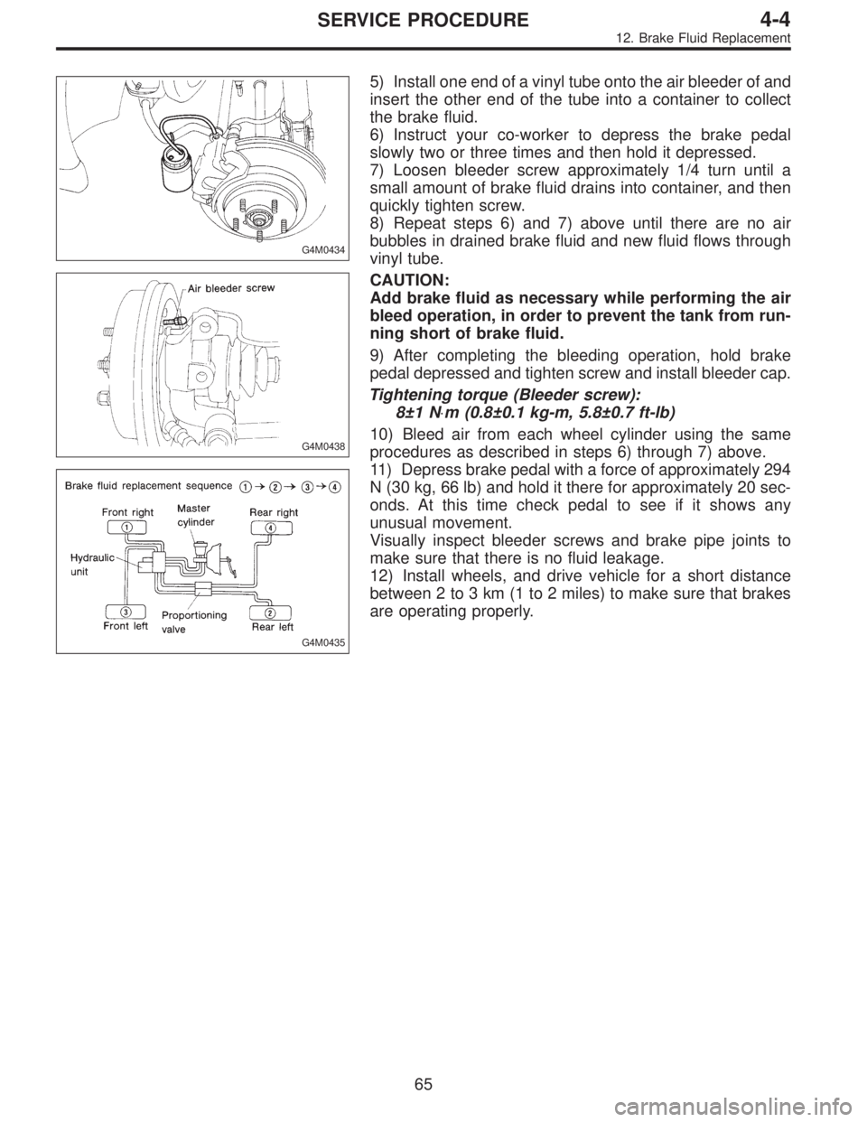
G4M0434
G4M0438
G4M0435
5) Install one end of a vinyl tube onto the air bleeder of and
insert the other end of the tube into a container to collect
the brake fluid.
6) Instruct your co-worker to depress the brake pedal
slowly two or three times and then hold it depressed.
7) Loosen bleeder screw approximately 1/4 turn until a
small amount of brake fluid drains into container, and then
quickly tighten screw.
8) Repeat steps 6) and 7) above until there are no air
bubbles in drained brake fluid and new fluid flows through
vinyl tube.
CAUTION:
Add brake fluid as necessary while performing the air
bleed operation, in order to prevent the tank from run-
ning short of brake fluid.
9) After completing the bleeding operation, hold brake
pedal depressed and tighten screw and install bleeder cap.
Tightening torque (Bleeder screw):
8±1 N⋅m (0.8±0.1 kg-m, 5.8±0.7 ft-lb)
10) Bleed air from each wheel cylinder using the same
procedures as described in steps 6) through 7) above.
11) Depress brake pedal with a force of approximately 294
N (30 kg, 66 lb) and hold it there for approximately 20 sec-
onds. At this time check pedal to see if it shows any
unusual movement.
Visually inspect bleeder screws and brake pipe joints to
make sure that there is no fluid leakage.
12) Install wheels, and drive vehicle for a short distance
between 2 to 3 km (1 to 2 miles) to make sure that brakes
are operating properly.
65
4-4SERVICE PROCEDURE
12. Brake Fluid Replacement
Page 1297 of 2890
11) Operate FRO (Front Right Outlet) valve and RLO
(Rear Left Outlet) valve to bleed air from hydraulic unit
outlet circuit.
(1) Press TCS OFF switch while depressing brake
pedal.
(2) Make sure ABS warning light illuminates.
(3) Repeatedly depress and release brake pedal 10
times or more while pressing TCS OFF switch.
NOTE:
�Air comes out from reservoir tank.
12) Operate FLO (Front Left Outlet) valve and RRO (Rear
Right Outlet) valve to bleed air from hydraulic unit outlet
circuit.
(1) Press TCS OFF switch while depressing brake
pedal.
(2) Make sure TCS warning light illuminates.
(3) Repeatedly depress and release brake pedal 10
times or more while pressing TCS OFF switch.
NOTE:
�Air comes out from reservoir tank.
�The operations in steps 11) and 12) above can be
switched with each other by operating brake pedal (stop
light switch) while pressing TCS OFF switch.
�Repeat procedures 11) and 12) until air no longer comes
out of reservoir tank.
13) Perform these steps for the brakes connecting to the
secondary chamber of master cylinder, first, and then for
the ones connecting to primary chamber. With all proce-
dures completed, fully depress the brake pedal and keep
it in that position for approximately 20 seconds to make
sure that there is no leak evident in the entire system.
14) Turn ignition switch OFF.
15) Perform TCS sequence control.
[W20F0].>
88
4-4SERVICE PROCEDURE
19. Air Bleeding (With TCS model)
Page 1298 of 2890
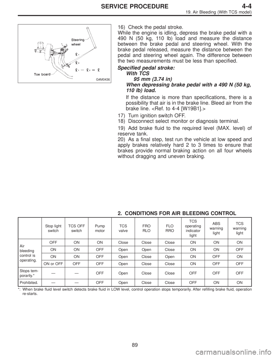
G4M0436
16) Check the pedal stroke.
While the engine is idling, depress the brake pedal with a
490 N (50 kg, 110 lb) load and measure the distance
between the brake pedal and steering wheel. With the
brake pedal released, measure the distance between the
pedal and steering wheel again. The difference between
the two measurements must be less than specified.
Specified pedal stroke:
With TCS
95 mm (3.74 in)
When depressing brake pedal with a 490 N (50 kg,
110 lb) load.
If the distance is more than specifications, there is a
possibility that air is in the brake line. Bleed air from the
brake line.
17) Turn ignition switch OFF.
18) Disconnect select monitor or diagnosis terminal.
19) Add brake fluid to the required level (MAX. level) of
reserve tank.
20) As a final step, test run the vehicle at low speed and
apply brakes relatively hard 2 to 3 times to ensure that
brakes provide normal braking action on all four wheels
without dragging and uneven braking.
2. CONDITIONS FOR AIR BLEEDING CONTROL
Stop light
switchTCS OFF
switchPump
motorTCS
valveFRO
RLOFLO
RROTCS
operating
indicator
lightABS
warning
lightTCS
warning
light
Air
bleeding
control is
operating.OFF ON ON Close Close Close ON ON ON
ON ON OFF Open Open Close ON ON OFF
ON ON OFF Open Close Open ON OFF ON
ON or OFF OFF OFF Open Close Close ON OFF OFF
Stops tem-
porarily.*——OFF Open Close Close OFF OFF OFF
Prohibited.——OFF Open Close Close OFF ON ON
*: When brake fluid level switch detects brake fluid in LOW level, control operation stops temporarily. After refilling brake fluid, operation
re-starts.
89
4-4SERVICE PROCEDURE
19. Air Bleeding (With TCS model)
Page 1826 of 2890
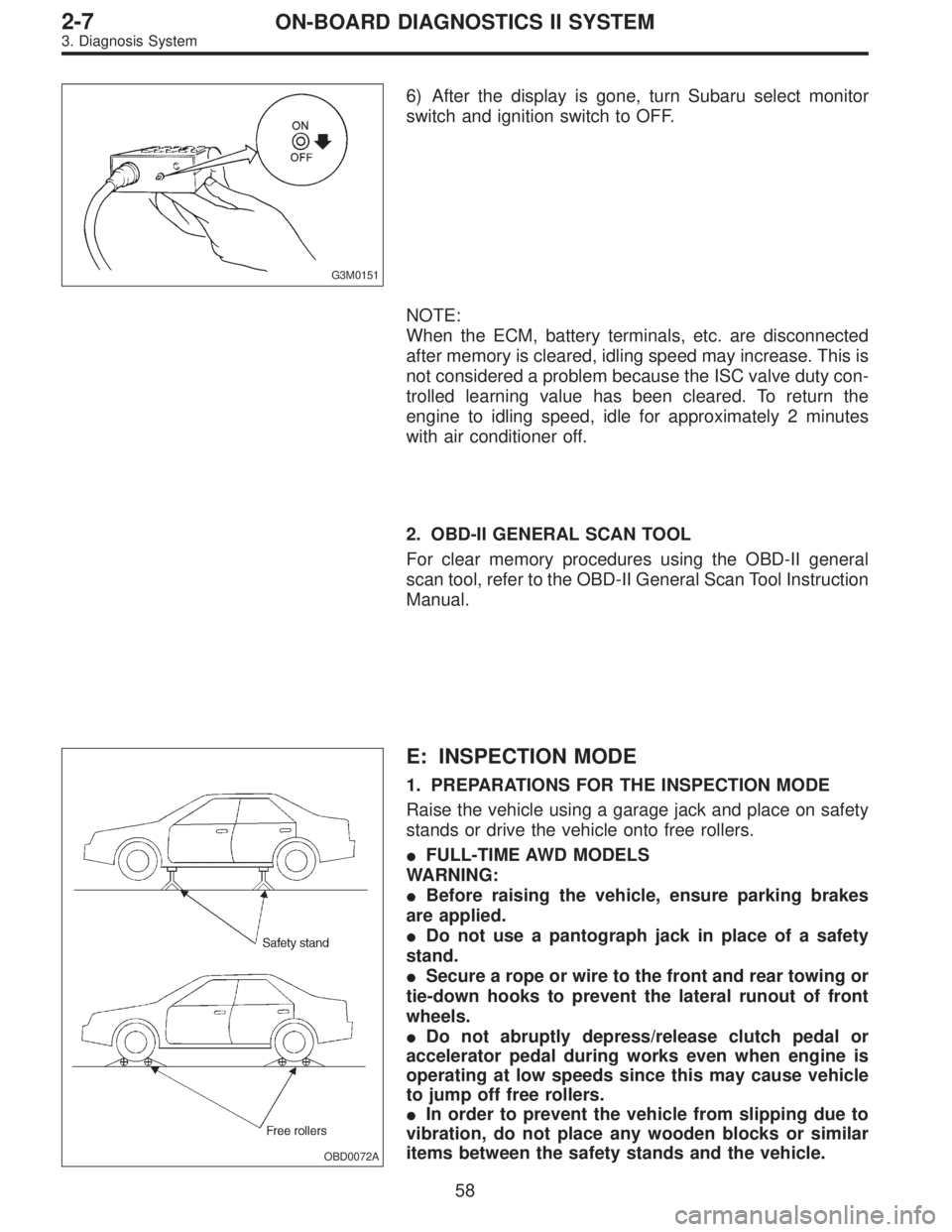
G3M0151
6) After the display is gone, turn Subaru select monitor
switch and ignition switch to OFF.
NOTE:
When the ECM, battery terminals, etc. are disconnected
after memory is cleared, idling speed may increase. This is
not considered a problem because the ISC valve duty con-
trolled learning value has been cleared. To return the
engine to idling speed, idle for approximately 2 minutes
with air conditioner off.
2. OBD-II GENERAL SCAN TOOL
For clear memory procedures using the OBD-II general
scan tool, refer to the OBD-II General Scan Tool Instruction
Manual.
OBD0072A
E: INSPECTION MODE
1. PREPARATIONS FOR THE INSPECTION MODE
Raise the vehicle using a garage jack and place on safety
stands or drive the vehicle onto free rollers.
�FULL-TIME AWD MODELS
WARNING:
�Before raising the vehicle, ensure parking brakes
are applied.
�Do not use a pantograph jack in place of a safety
stand.
�Secure a rope or wire to the front and rear towing or
tie-down hooks to prevent the lateral runout of front
wheels.
�Do not abruptly depress/release clutch pedal or
accelerator pedal during works even when engine is
operating at low speeds since this may cause vehicle
to jump off free rollers.
�In order to prevent the vehicle from slipping due to
vibration, do not place any wooden blocks or similar
items between the safety stands and the vehicle.
58
2-7ON-BOARD DIAGNOSTICS II SYSTEM
3. Diagnosis System
Page 1827 of 2890
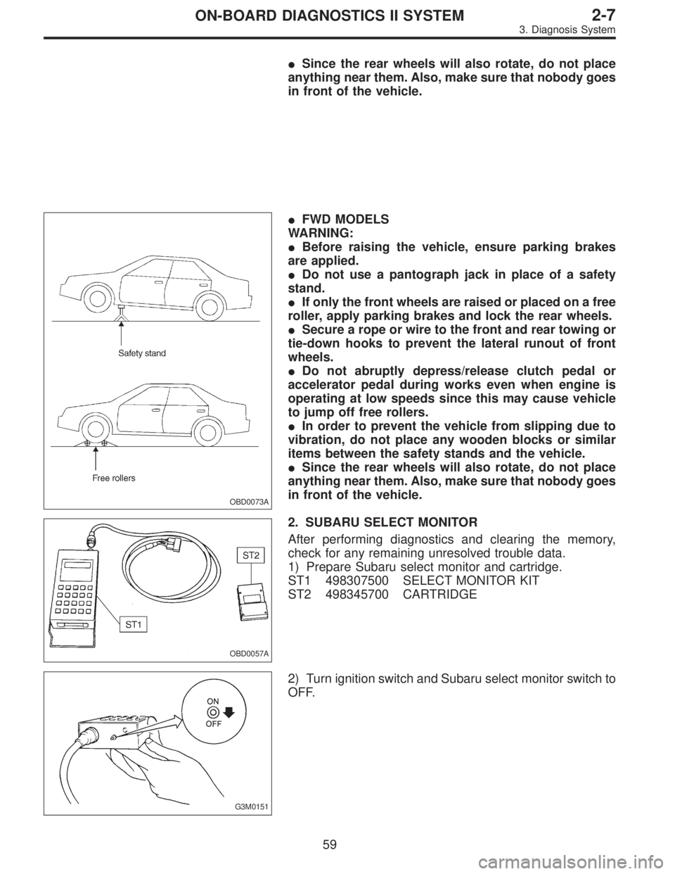
�Since the rear wheels will also rotate, do not place
anything near them. Also, make sure that nobody goes
in front of the vehicle.
OBD0073A
�FWD MODELS
WARNING:
�Before raising the vehicle, ensure parking brakes
are applied.
�Do not use a pantograph jack in place of a safety
stand.
�If only the front wheels are raised or placed on a free
roller, apply parking brakes and lock the rear wheels.
�Secure a rope or wire to the front and rear towing or
tie-down hooks to prevent the lateral runout of front
wheels.
�Do not abruptly depress/release clutch pedal or
accelerator pedal during works even when engine is
operating at low speeds since this may cause vehicle
to jump off free rollers.
�In order to prevent the vehicle from slipping due to
vibration, do not place any wooden blocks or similar
items between the safety stands and the vehicle.
�Since the rear wheels will also rotate, do not place
anything near them. Also, make sure that nobody goes
in front of the vehicle.
OBD0057A
2. SUBARU SELECT MONITOR
After performing diagnostics and clearing the memory,
check for any remaining unresolved trouble data.
1) Prepare Subaru select monitor and cartridge.
ST1 498307500 SELECT MONITOR KIT
ST2 498345700 CARTRIDGE
G3M0151
2) Turn ignition switch and Subaru select monitor switch to
OFF.
59
2-7ON-BOARD DIAGNOSTICS II SYSTEM
3. Diagnosis System
Page 2212 of 2890
1. Supplemental Restraint System
“Airbag”
Airbag system wiring harness is routed near the ABS/TCS
control module, ABS sensor and hydraulic control unit.
CAUTION:
�All Airbag system wiring harness and connectors
are colored yellow. Do not use electrical test equip-
ment on these circuit.
�Be careful not to damage Airbag system wiring har-
ness when servicing the ABS/TCS control module,
ABS sensor and hydraulic control unit.
2. Pre-inspection
Before performing diagnostics, check the following items
which might affect ABS/TCS problems:
A: MECHANICAL INSPECTION
1. POWER SUPPLY
1) Measure battery voltage and specific gravity of electro-
lyte.
Standard voltage: 12 V, or more
Specific gravity: Above 1.260
2) Check the condition of the main and other fuses, and
harnesses and connectors. Also check for proper ground-
ing.
2. BRAKE FLUID
1) Check brake fluid level.
2) Check brake fluid leakage.
3. BRAKE DRAG
Check brake drag.
4. BRAKE PAD AND ROTOR
Check brake pad and rotor.
5. TIRE SPECIFICATIONS, TIRE WEAR AND AIR
PRESSURE
Check tire specifications, tire wear and air pressure.
to 4-2 [S1A0].>
2
4-4bBRAKES
1. Supplemental Restraint System“Airbag”- 2. Pre-inspection
Page 2213 of 2890
1. Supplemental Restraint System
“Airbag”
Airbag system wiring harness is routed near the ABS/TCS
control module, ABS sensor and hydraulic control unit.
CAUTION:
�All Airbag system wiring harness and connectors
are colored yellow. Do not use electrical test equip-
ment on these circuit.
�Be careful not to damage Airbag system wiring har-
ness when servicing the ABS/TCS control module,
ABS sensor and hydraulic control unit.
2. Pre-inspection
Before performing diagnostics, check the following items
which might affect ABS/TCS problems:
A: MECHANICAL INSPECTION
1. POWER SUPPLY
1) Measure battery voltage and specific gravity of electro-
lyte.
Standard voltage: 12 V, or more
Specific gravity: Above 1.260
2) Check the condition of the main and other fuses, and
harnesses and connectors. Also check for proper ground-
ing.
2. BRAKE FLUID
1) Check brake fluid level.
2) Check brake fluid leakage.
3. BRAKE DRAG
Check brake drag.
4. BRAKE PAD AND ROTOR
Check brake pad and rotor.
5. TIRE SPECIFICATIONS, TIRE WEAR AND AIR
PRESSURE
Check tire specifications, tire wear and air pressure.
to 4-2 [S1A0].>
2
4-4bBRAKES
1. Supplemental Restraint System“Airbag”- 2. Pre-inspection
Page 2214 of 2890
B: ELECTRICAL INSPECTION
1. WARNING LAMP ILLUMINATION PATTERN
B4M0372A
2. DISPLAY SYSTEM TYPE AND LIGHTING
CONDITIONS
�: Illuminated
Mode
ABS warning
TCS warning
TCS OFF
TCS operating
Lighting conditions
Bulb check��Illuminated with IGN. ON, extinguished with E/G RUN
�Illuminated with IGN. ON, extinguished after a few seconds.
�Illuminated with IGN. ON, extinguished after 1 second.
ABS failure��Illuminated during ABS failure (ABS and TCS functions stop)
TCS failure�Illuminated during TCS failure (Only TCS functions stop)
TCS OFF
�Illuminated when TCS operation is prohibited by E/G (low temperature, high
temperature, etc.); illuminated during TCS OFF conditions resulting from operation
of TCS OFF SW.
TCS operation�Illuminated during TCS operation
Pad temperature warning
�Illuminated when pad temperature reaches 400°C (752°F) or more when TCS is
functioning, and extinguished when temperature drops below 350°C (662°F).
3
4-4bBRAKES
2. Pre-inspection