Page 480 of 2890
B2M0724
13) Connect connector to front oxygen sensor.
B2M0725
14) Connect connector to rear oxygen sensor. (California
2200 cc model only)
G2M0302
15) Install pitching stopper.
Tightening torque:
T1: 49±5 N⋅m (5.0±0.5 kg-m, 36.2±3.6 ft-lb)
T2: 57±10 N⋅m (5.8±1.0 kg-m, 42±7 ft-lb)
B2M0320
16) Install radiator upper brackets.
Tightening torque:
12±3 N⋅m (1.2±0.3 kg-m, 8.7±2.2 ft-lb)
B2M0321
17) Install air intake duct.
18) Fill engine oil through filler pipe up to upper point of
level gauge.
Engine oil capacity:
2200 cc ; Upper level
4.0�(4.2 US qt, 3.5 Imp qt)
Lower level
3.0�(3.2 US qt, 2.6 Imp qt)
2500 cc ; Upper level
4.5�(4.8 US qt, 4.0 Imp qt)
14
2-4SERVICE PROCEDURE
2. Oil Pan and Oil Strainer
Page 485 of 2890
 Approx. 6.1 (6.4, 5.4)
E")
1. Engine Cooling System
A: SPECIFICATIONS
1. 2200 cc MODEL
Cooling systemElectric fan + Forced engine coolant circulation
system
Total engine coolant capacity�(US qt, Imp qt) Approx. 6.1 (6.4, 5.4)
Engine
coolant
pumpTypeCentrifugal impeller type
Discharge performance IDischarge 20�(5.3 US gal, 4.4 Imp gal)/min.
Pump speed—total engine cool-
ant head760 rpm — 0.3 mAq (1.0 ftAq)
Engine coolant temperature 85°C (185°F)
Discharge performance IIDischarge 100�(26.4 US gal, 22.0 Imp gal)/min.
Pump speed—total engine cool-
ant head3,000 rpm — 5.0 mAq (16.4 ftAq)
Engine coolant temperature 85°C (185°F)
Discharge performance IIIDischarge 200�(52.8 US gal, 44.0 Imp gal)/min.
Pump speed—total engine cool-
ant head6,000 rpm — 23.0 mAq (75.5 ftAq)
Engine coolant temperature 85°C (185°F)
Impeller diameter 76 mm (2.99 in)
Number of impeller vanes 8
Pump pulley diameter 60 mm (2.36 in)
ThermostatTypeWax pellet type
Starts to open 76 — 80°C (169 — 176°F)
Fully opened91°C (196°F)
Valve lift9.0 mm (0.354 in) or more
Valve bore35 mm (1.38 in)
Radiator fanMotor120 W
Fan diameter x Blade 320 mm (12.60 in) x 5
RadiatorTypeCross flow, pressure type
Core dimensions670x361x16mm
(26.38 x 14.21 x 0.63 in)
Pressure range in which cap valve is openAbove: 88±10 kPa
(0.9±0.1 kg/cm
2, 12.8±1.4 psi)
Below: �4.9 to �9.8 kPa
(�0.05 to �0.1 kg/cm
2, �0.7 to �1.4 psi)
FinsCorrugated fin type
Reservoir
tankCapacity 0.5�(0.5 US qt, 0.4 Imp qt)
2
2-5SPECIFICATIONS AND SERVICE DATA
1. Engine Cooling System
Page 486 of 2890
 Approx. 6.1 (6.4, 5.4)
Engine
coolant
pumpTypeCentrifugal impeller")
2. 2500 cc MODEL
Cooling systemElectric fan + Forced engine coolant circulation
system
Total engine coolant capacity�(US qt, Imp qt) Approx. 6.1 (6.4, 5.4)
Engine
coolant
pumpTypeCentrifugal impeller type
Discharge performance IDischarge 20�(5.3 US gal, 4.4 Imp gal)/min.
Pump speed—total engine cool-
ant head760 rpm—0.3 mAq (1.0 ftAq)
Engine coolant temperature 85°C (185°F)
Discharge performance IIDischarge 100�(26.4 US gal, 22.0 Imp gal)/min.
Pump speed—total engine cool-
ant head3,000 rpm—5.0 mAq (16.4 ftAq)
Engine coolant temperature 85°C (185°F)
Discharge performance IIIDischarge 200�(52.8 US gal, 44.0 Imp gal)/min.
Pump speed—total engine cool-
ant head6,000 rpm—23.0 mAq (75.5 ftAq)
Engine coolant temperature 85°C (185°F)
Impeller diameter 76 mm (2.99 in)
Number of impeller vanes 8
Pump pulley diameter 60 mm (2.36 in)
ThermostatTypeWax pellet type
Starts to open 76—80°C (169—176°F)
Fully opened91°C (196°F)
Valve lift9.0 mm (0.354 in) or more
Valve bore35 mm (1.38 in)
Radiator fanMotor120 W (main fan)
140 W (sub fan)
Fan diameter x Blade340 mm (13.39 in) x 5 (main fan)
280 mm (11.02 in) x 4 (sub fan)
RadiatorTypeCross flow, pressure type
Core dimensions670x361x25mm
(26.38 x 14.21 x 0.98 in)
Pressure range in which cap valve is openAbove: 88±10 kPa
(0.9±0.1 kg/cm
2, 12.8±1.4 psi)
Below:�4.9 to�9.8 kPa
(�0.05 to�0.1 kg/cm
2,�0.7 to�1.4 psi)
FinsCorrugated fin type
Reservoir
tankCapacity 0.5�(0.5 US qt, 0.4 Imp qt)
B: SERVICE DATA
Engine
coolant
pumpClearance between impeller and caseStandard
Limit0.5—0.7 mm (0.020—0.028 in)
1.0 mm (0.039 in)
“Thrust”runout of impeller end 0.5 mm (0.020 in)
3
2-5SPECIFICATIONS AND SERVICE DATA
1. Engine Cooling System
Page 488 of 2890
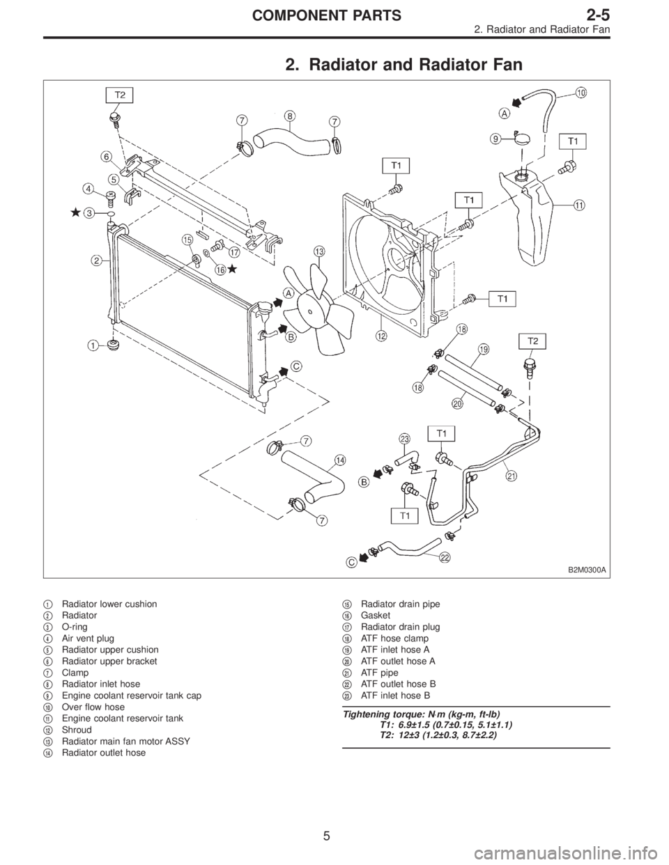
2. Radiator and Radiator Fan
B2M0300A
�1Radiator lower cushion
�
2Radiator
�
3O-ring
�
4Air vent plug
�
5Radiator upper cushion
�
6Radiator upper bracket
�
7Clamp
�
8Radiator inlet hose
�
9Engine coolant reservoir tank cap
�
10Over flow hose
�
11Engine coolant reservoir tank
�
12Shroud
�
13Radiator main fan motor ASSY
�
14Radiator outlet hose�
15Radiator drain pipe
�
16Gasket
�
17Radiator drain plug
�
18ATF hose clamp
�
19ATF inlet hose A
�
20ATF outlet hose A
�
21ATF pipe
�
22ATF outlet hose B
�
23ATF inlet hose B
Tightening torque: N⋅m (kg-m, ft-lb)
T1: 6.9±1.5 (0.7±0.15, 5.1±1.1)
T2: 12±3 (1.2±0.3, 8.7±2.2)
5
2-5COMPONENT PARTS
2. Radiator and Radiator Fan
Page 490 of 2890
1. On-Car Service
A: DRAINING OF ENGINE COOLANT
1) Lift-up the vehicle.
B2M0133A
2) Fit vinyl tube to drain pipe.
B2M0015A
3) Loosen drain cock to drain engine coolant into con-
tainer.
NOTE:
Remove radiator cap so that engine coolant will drain
faster.
B2M0301
B: FILLING OF ENGINE COOLANT
1) Remove air vent plug from radiator.
B2M0135
2) Fill engine coolant into radiator up to filler neck position.
7
2-5SERVICE PROCEDURE
1. On-Car Service
Page 491 of 2890
 Fill engine coolant into reservoir tank up to upper level.
4) Attach radiator cap and reservoir tank cap properly.
5) Install air vent plug.
6) Warm-up engine completely for more than five")
B2M0140
3) Fill engine coolant into reservoir tank up to upper level.
4) Attach radiator cap and reservoir tank cap properly.
5) Install air vent plug.
6) Warm-up engine completely for more than five minutes
at 2,000 to 3,000 rpm.
7) Stop engine and wait until temperature drops to a safe
level.
8) If engine coolant level drops in radiator, add engine
coolant to filler neck position.
9) If engine coolant level drops from upper level of reser-
voir tank, add engine coolant to upper level.
10) Attach radiator cap and reservoir tank cap properly.
B2M0136
C: CHECKING OF COOLING SYSTEM
1) Remove radiator cap, top off radiator, and attach tester
to radiator in place of cap.
2) Apply a pressure of 157 kPa (1.6 kg/cm
2, 23 psi) to
radiator to check if:
(1) Engine coolant leaks at/around radiator.
(2) Engine coolant leaks at/around hoses or connec-
tions.
CAUTION:
�Engine should be off.
�Wipe engine coolant from check points in advance.
�Be careful to prevent engine coolant from spurting
out when removing tester.
�Be careful also not to deform filler neck of radiator
when installing or removing tester.
8
2-5SERVICE PROCEDURE
1. On-Car Service
Page 499 of 2890
G2M0223
5. Radiator Cap
A: INSPECTION
1) Attach radiator cap to tester.
2) Increase pressure until tester gauge pointer stops.
Radiator cap is functioning properly if it holds the service
limit pressure for five to six seconds.
Standard pressure:
78—98 kPa (0.8—1.0 kg/cm
2,11—14 psi)
Service limit pressure:
69 kPa (0.7 kg/cm
2, 10 psi)
CAUTION:
Be sure to remove foreign matter and rust from the cap
in advance; otherwise, results of pressure test will be
incorrect.
G2M0263
6. Radiator Fan and Fan Motor
A: REMOVAL
1) Disconnect ground cable from battery terminal.
2) Disconnect connector of fan motor.
G2M0224
3) Remove reservoir tank.
B2M0308
4) Remove four bolts holding shroud to radiator.
16
2-5SERVICE PROCEDURE
5. Radiator Cap - 6. Radiator Fan and Fan Motor
Page 600 of 2890
G2M0223
5. Radiator Cap
A: INSPECTION
1) Attach radiator cap to tester.
2) Increase pressure until tester gauge pointer stops.
Radiator cap is functioning properly if it holds the service
limit pressure for five to six seconds.
Standard pressure:
78—98 kPa (0.8—1.0 kg/cm
2,11—14 psi)
Service limit pressure:
69 kPa (0.7 kg/cm
2, 10 psi)
CAUTION:
Be sure to remove foreign matter and rust from the cap
in advance; otherwise, results of pressure test will be
incorrect.
G2M0263
6. Radiator Fan and Fan Motor
A: REMOVAL
1) Disconnect ground cable from battery terminal.
2) Disconnect connector of fan motor.
G2M0224
3) Remove reservoir tank.
B2M0308
4) Remove four bolts holding shroud to radiator.
16
2-5SERVICE PROCEDURE
5. Radiator Cap - 6. Radiator Fan and Fan Motor
 Connect connector to front oxygen sensor.
B2M0725
14) Connect connector to rear oxygen sensor. (California
2200 cc model only)
G2M0302
15) Install pitching stopper.
Tightening torque:
T1:")
 Lift-up the vehicle.
B2M0133A
2) Fit vinyl tube to drain pipe.
B2M0015A
3) Loosen drain cock to drain engine coolant into con-
tainer.
NOTE:
Remove r")
 Attach radiator cap to tester.
2) Increase pressure until tester gauge pointer stops.
Radiator cap is functioning properly if it holds the service
limit pressu")
 Attach radiator cap to tester.
2) Increase pressure until tester gauge pointer stops.
Radiator cap is functioning properly if it holds the service
limit pressu")