Page 601 of 2890
G2M0223
5. Radiator Cap
A: INSPECTION
1) Attach radiator cap to tester.
2) Increase pressure until tester gauge pointer stops.
Radiator cap is functioning properly if it holds the service
limit pressure for five to six seconds.
Standard pressure:
78—98 kPa (0.8—1.0 kg/cm
2,11—14 psi)
Service limit pressure:
69 kPa (0.7 kg/cm
2, 10 psi)
CAUTION:
Be sure to remove foreign matter and rust from the cap
in advance; otherwise, results of pressure test will be
incorrect.
G2M0263
6. Radiator Fan and Fan Motor
A: REMOVAL
1) Disconnect ground cable from battery terminal.
2) Disconnect connector of fan motor.
G2M0224
3) Remove reservoir tank.
B2M0308
4) Remove four bolts holding shroud to radiator.
16
2-5SERVICE PROCEDURE
5. Radiator Cap - 6. Radiator Fan and Fan Motor
Page 829 of 2890
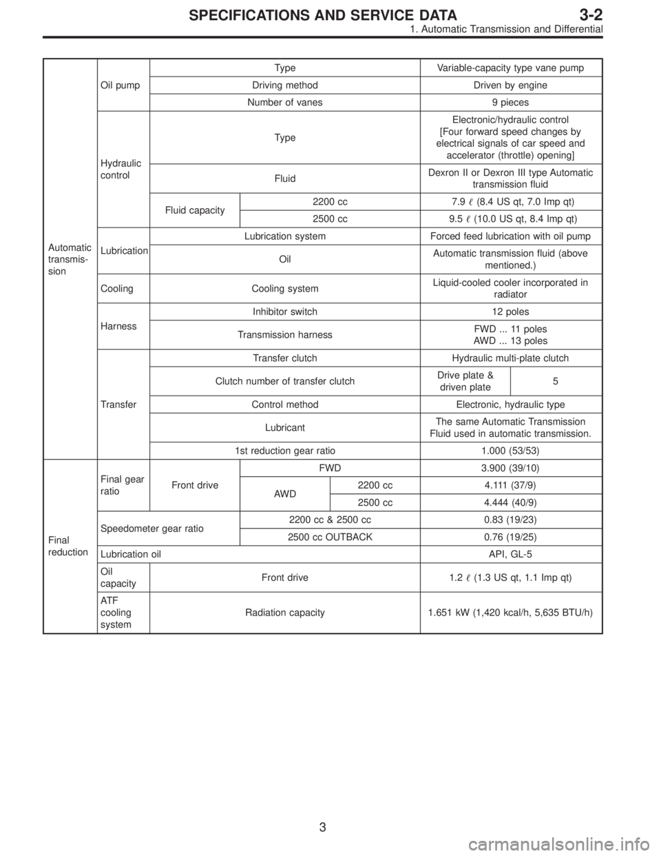
Automatic
transmis-
sionOil pumpType Variable-capacity type vane pump
Driving method Driven by engine
Number of vanes 9 pieces
Hydraulic
controlTypeElectronic/hydraulic control
[Four forward speed changes by
electrical signals of car speed and
accelerator (throttle) opening]
FluidDexron II or Dexron III type Automatic
transmission fluid
Fluid capacity2200 cc 7.9�(8.4 US qt, 7.0 Imp qt)
2500 cc 9.5�(10.0 US qt, 8.4 Imp qt)
LubricationLubrication system Forced feed lubrication with oil pump
OilAutomatic transmission fluid (above
mentioned.)
Cooling Cooling systemLiquid-cooled cooler incorporated in
radiator
HarnessInhibitor switch 12 poles
Transmission harnessFWD ... 11 poles
AWD ... 13 poles
TransferTransfer clutch Hydraulic multi-plate clutch
Clutch number of transfer clutchDrive plate &
driven plate5
Control method Electronic, hydraulic type
LubricantThe same Automatic Transmission
Fluid used in automatic transmission.
1st reduction gear ratio 1.000 (53/53)
Final
reductionFinal gear
ratioFront driveFWD 3.900 (39/10)
AWD2200 cc 4.111 (37/9)
2500 cc 4.444 (40/9)
Speedometer gear ratio2200 cc & 2500 cc 0.83 (19/23)
2500 cc OUTBACK 0.76 (19/25)
Lubrication oilAPI, GL-5
Oil
capacityFront drive 1.2�(1.3 US qt, 1.1 Imp qt)
AT F
cooling
systemRadiation capacity 1.651 kW (1,420 kcal/h, 5,635 BTU/h)
3
3-2SPECIFICATIONS AND SERVICE DATA
1. Automatic Transmission and Differential
Page 1375 of 2890
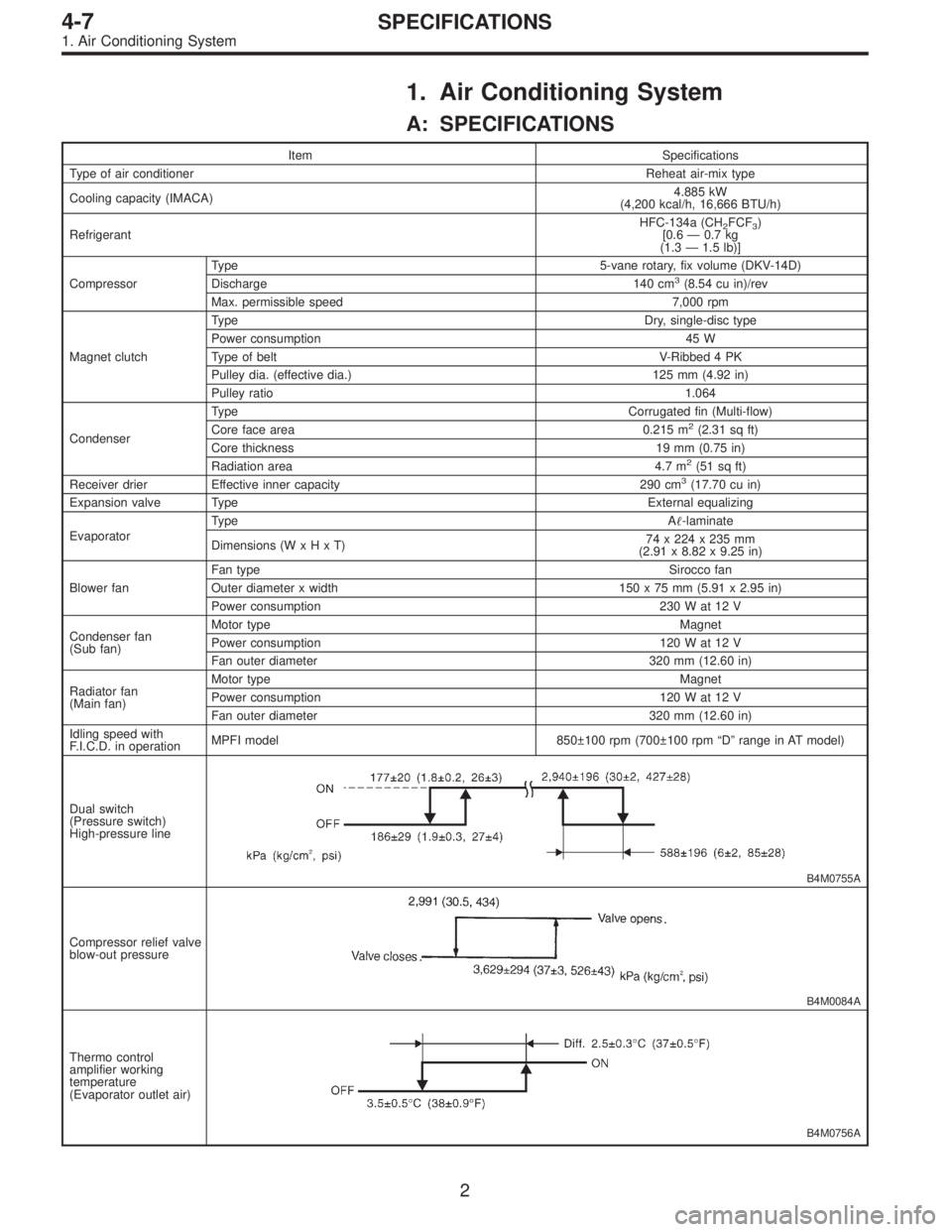
1. Air Conditioning System
A: SPECIFICATIONS
Item Specifications
Type of air conditionerReheat air-mix type
Cooling capacity (IMACA)4.885 kW
(4,200 kcal/h, 16,666 BTU/h)
RefrigerantHFC-134a (CH
2FCF3)
[0.6 — 0.7 kg
(1.3 — 1.5 lb)]
CompressorType 5-vane rotary, fix volume (DKV-14D)
Discharge 140 cm
3(8.54 cu in)/rev
Max. permissible speed 7,000 rpm
Magnet clutchTy p eDry, single-disc type
Power consumption 45 W
Type of belt V-Ribbed 4 PK
Pulley dia. (effective dia.) 125 mm (4.92 in)
Pulley ratio1.064
CondenserType Corrugated fin (Multi-flow)
Core face area 0.215 m
2(2.31 sq ft)
Core thickness 19 mm (0.75 in)
Radiation area 4.7 m
2(51 sq ft)
Receiver drier Effective inner capacity 290 cm3(17.70 cu in)
Expansion valve TypeExternal equalizing
EvaporatorTy p eA�-laminate
Dimensions (W x H x T)74 x 224 x 235 mm
(2.91 x 8.82 x 9.25 in)
Blower fanFan typeSirocco fan
Outer diameter x width 150 x 75 mm (5.91 x 2.95 in)
Power consumption 230 W at 12 V
Condenser fan
(Sub fan)Motor typeMagnet
Power consumption 120 W at 12 V
Fan outer diameter 320 mm (12.60 in)
Radiator fan
(Main fan)Motor typeMagnet
Power consumption 120 W at 12 V
Fan outer diameter 320 mm (12.60 in)
Idling speed with
F.I.C.D. in operationMPFI model 850±100 rpm (700±100 rpm “D” range in AT model)
Dual switch
(Pressure switch)
High-pressure line
B4M0755A
Compressor relief valve
blow-out pressure
B4M0084A
Thermo control
amplifier working
temperature
(Evaporator outlet air)
B4M0756A
2
4-7SPECIFICATIONS
1. Air Conditioning System
Page 1413 of 2890
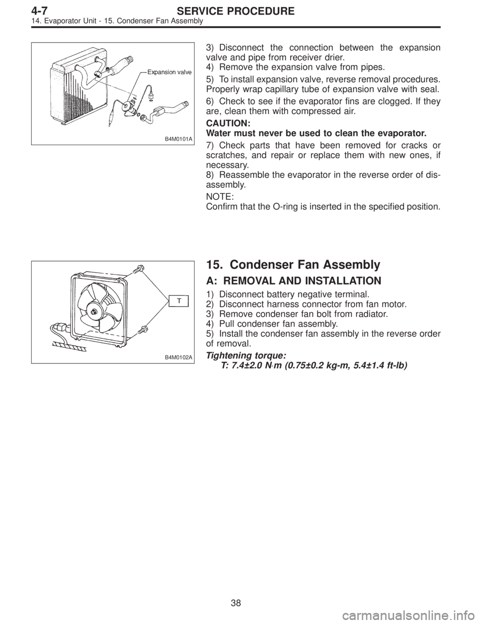
B4M0101A
3) Disconnect the connection between the expansion
valve and pipe from receiver drier.
4) Remove the expansion valve from pipes.
5) To install expansion valve, reverse removal procedures.
Properly wrap capillary tube of expansion valve with seal.
6) Check to see if the evaporator fins are clogged. If they
are, clean them with compressed air.
CAUTION:
Water must never be used to clean the evaporator.
7) Check parts that have been removed for cracks or
scratches, and repair or replace them with new ones, if
necessary.
8) Reassemble the evaporator in the reverse order of dis-
assembly.
NOTE:
Confirm that the O-ring is inserted in the specified position.
B4M0102A
15. Condenser Fan Assembly
A: REMOVAL AND INSTALLATION
1) Disconnect battery negative terminal.
2) Disconnect harness connector from fan motor.
3) Remove condenser fan bolt from radiator.
4) Pull condenser fan assembly.
5) Install the condenser fan assembly in the reverse order
of removal.
Tightening torque:
T: 7.4±2.0 N⋅m (0.75±0.2 kg-m, 5.4±1.4 ft-lb)
38
4-7SERVICE PROCEDURE
14. Evaporator Unit - 15. Condenser Fan Assembly
Page 1414 of 2890
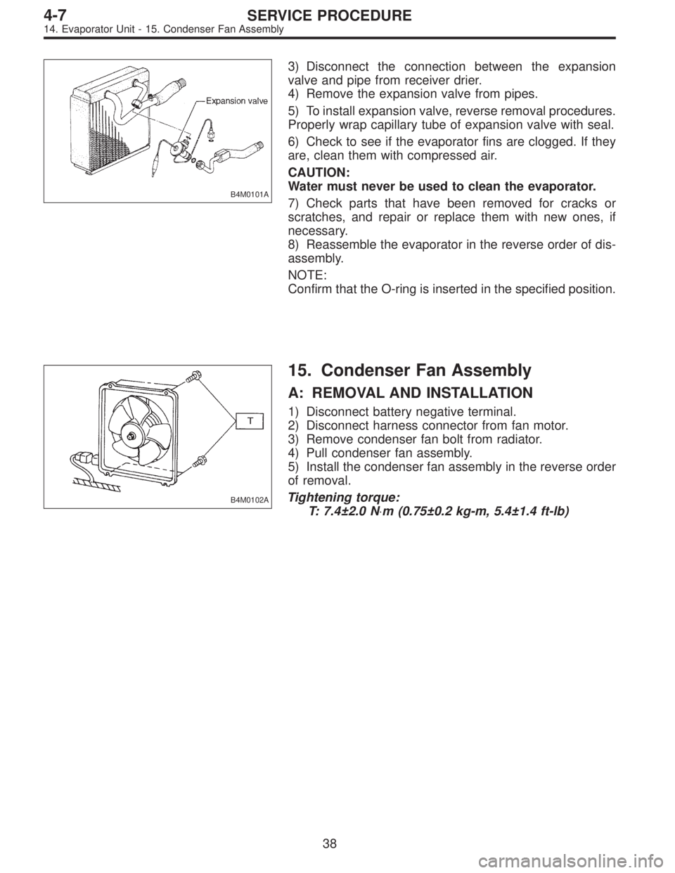
B4M0101A
3) Disconnect the connection between the expansion
valve and pipe from receiver drier.
4) Remove the expansion valve from pipes.
5) To install expansion valve, reverse removal procedures.
Properly wrap capillary tube of expansion valve with seal.
6) Check to see if the evaporator fins are clogged. If they
are, clean them with compressed air.
CAUTION:
Water must never be used to clean the evaporator.
7) Check parts that have been removed for cracks or
scratches, and repair or replace them with new ones, if
necessary.
8) Reassemble the evaporator in the reverse order of dis-
assembly.
NOTE:
Confirm that the O-ring is inserted in the specified position.
B4M0102A
15. Condenser Fan Assembly
A: REMOVAL AND INSTALLATION
1) Disconnect battery negative terminal.
2) Disconnect harness connector from fan motor.
3) Remove condenser fan bolt from radiator.
4) Pull condenser fan assembly.
5) Install the condenser fan assembly in the reverse order
of removal.
Tightening torque:
T: 7.4±2.0 N⋅m (0.75±0.2 kg-m, 5.4±1.4 ft-lb)
38
4-7SERVICE PROCEDURE
14. Evaporator Unit - 15. Condenser Fan Assembly
Page 1839 of 2890
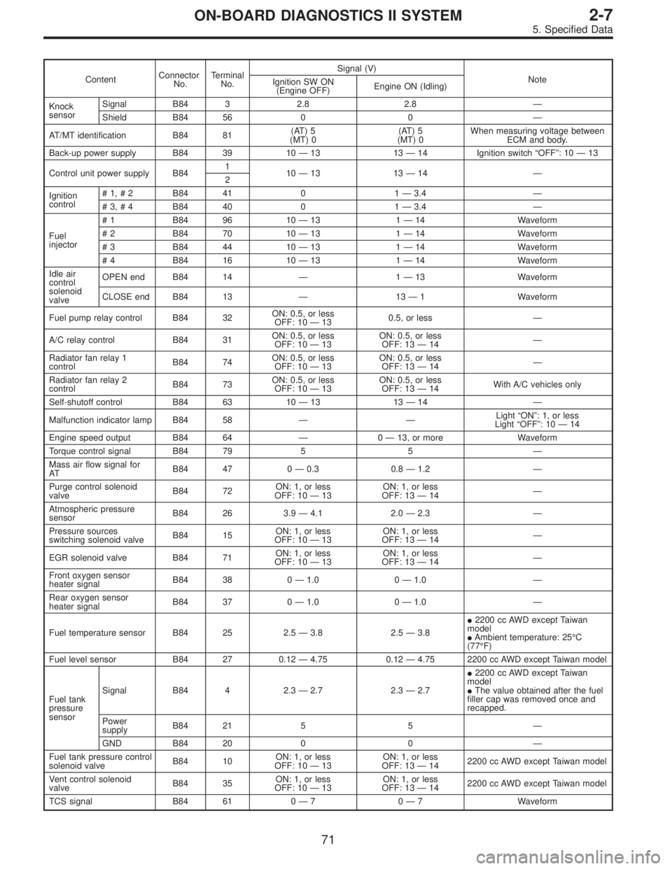
ContentConnector
No.Terminal
No.Signal (V)
Note
Ignition SW ON
(Engine OFF)Engine ON (Idling)
Knock
sensorSignal B84 3 2.8 2.8—
Shield B84 56 0 0—
AT/MT identification B84 81(AT) 5
(MT) 0(AT) 5
(MT) 0When measuring voltage between
ECM and body.
Back-up power supply B84 39 10—13 13—14 Ignition switch“OFF”:10—13
Control unit power supply B841
10—13 13—14—
2
Ignition
control#1,#2 B84 41 0 1—3.4—
#3,#4 B84 40 0 1—3.4—
Fuel
injector# 1 B84 96 10—13 1—14 Waveform
# 2 B84 70 10—13 1—14 Waveform
# 3 B84 44 10—13 1—14 Waveform
# 4 B84 16 10—13 1—14 Waveform
Idle air
control
solenoid
valveOPEN end B84 14—1—13 Waveform
CLOSE end B84 13—13—1 Waveform
Fuel pump relay control B84 32ON: 0.5, or less
OFF: 10—130.5, or less—
A/C relay control B84 31ON: 0.5, or less
OFF: 10—13ON: 0.5, or less
OFF: 13—14—
Radiator fan relay 1
controlB84 74ON: 0.5, or less
OFF: 10—13ON: 0.5, or less
OFF: 13—14—
Radiator fan relay 2
controlB84 73ON: 0.5, or less
OFF: 10—13ON: 0.5, or less
OFF: 13—14With A/C vehicles only
Self-shutoff control B84 63 10—13 13—14—
Malfunction indicator lamp B84 58——Light“ON”:1,orless
Light“OFF”:10—14
Engine speed output B84 64—0—13, or more Waveform
Torque control signal B84 79 5 5—
Mass air flow signal for
ATB84 47 0—0.3 0.8—1.2—
Purge control solenoid
valveB84 72ON: 1, or less
OFF: 10—13ON: 1, or less
OFF: 13—14—
Atmospheric pressure
sensorB84 26 3.9—4.1 2.0—2.3—
Pressure sources
switching solenoid valveB84 15ON: 1, or less
OFF: 10—13ON: 1, or less
OFF: 13—14—
EGR solenoid valve B84 71ON: 1, or less
OFF: 10—13ON: 1, or less
OFF: 13—14—
Front oxygen sensor
heater signalB84 38 0—1.0 0—1.0—
Rear oxygen sensor
heater signalB84 37 0—1.0 0—1.0—
Fuel temperature sensor B84 25 2.5—3.8 2.5—3.8�2200 cc AWD except Taiwan
model
�Ambient temperature: 25°C
(77°F)
Fuel level sensor B84 27 0.12—4.75 0.12—4.75 2200 cc AWD except Taiwan model
Fuel tank
pressure
sensorSignal B84 4 2.3—2.7 2.3—2.7�2200 cc AWD except Taiwan
model
�The value obtained after the fuel
filler cap was removed once and
recapped.
Power
supplyB84 21 5 5—
GND B84 20 0 0—
Fuel tank pressure control
solenoid valveB84 10ON: 1, or less
OFF: 10—13ON: 1, or less
OFF: 13—142200 cc AWD except Taiwan model
Vent control solenoid
valveB84 35ON: 1, or less
OFF: 10—13ON: 1, or less
OFF: 13—142200 cc AWD except Taiwan model
TCS signal B84 61 0—70—7 Waveform
71
2-7ON-BOARD DIAGNOSTICS II SYSTEM
5. Specified Data