Page 86 of 2890

Item
Page
P0705
ATRNG
Transmissionrange
sensor
circuit
malfunct")
ON-BOARD
DIAGNOSTICS
11
SYSTEM
[T11aoj
2-7
11
.
Diagnostics
Chart
with
Trouble
Code
DTC
No
.
Abbreviation
(Subaru
select
monitor)
Item
Page
P0705
ATRNG
Transmissionrange
sensor
circuit
malfunction
108
P0710
ATF
Transmission
fluid
temperature
sensor
circuit
malfunction
109
P0720
ATVSP
Output
speed
sensor
(vehicle
speed
sensor
1)
circuit
malfunction
110
P0725
ATNE
Engine
speed
input
circuit
malfunction
111
P0731
ATGR1
Gear
1
incorrect
ratio
P0732
ATGR2
Gear
2
incorrect
ratio
1
2
P0733
ATGR3
Gear
3
incorrect
ratio
1
P0734
ATGR4
Gear
4
incorrect
ratio
P0740
ATLU
-
F
Torque
converter
clutch
system
malfunction
114
P0743
ATLU
Torque
converter
clutch
system
(duty
solenoid
B)
electrical
115
P0748
ATPL
Pressure
control
solenoid
(duty
solenoid
A)
electrical
116
P0753
ATSFTi
Shift
solenoid
A
(shift
solenoid
1)
electrical
117
P0758
ATSFT2
Shift
solenoid
B
(shift
solenoid
2)
electrical
118
P0760
ATOVR
-
F
Shift
solenoid
C
(shift
solenoid
3)
malfunction
119
P0763
ATOVR
Shift
solenoid
C
(shift
solenoid
3)
electrical
120
P1100
ST
-
SW
Starter
switch
circuit
malfunction
121
P1101
N/P
-
SW
Neutral
position
switch
circuit
malfunction
122
P1102
BR
Pressure
sources
switching
solenoid
valve
circuit
malfunction
123
P1103
TRQ
Engine
torque
control
signal
circuit
malfunction
124
P1500
FAN
-
1
Radiator
fan
relay
1
circuit
malfunction
125
P1502
FAN
-
F
Radiator
fan
function
problem
126
P1700
ATTH
Throttle
position
sensor
circuit
malfunction
127
P1701
ATCRS
Cruise
control
set
signal
circuit
malfunction
128
P1702
ATDIAG
Automatic
transmission
diagnosis
inputsignal
circuit
malfunction
I
129
75
Page 120 of 2890
ON-BOARD
DIAGNOSTICS
II
SYSTEM
[Tiinooi
2-7
11
.
Diagnostics
Chart
with
Trouble
Code
AO
:
DTC
P0710
-
TRANSMISSION
FLUID
TEMPERATURE
SENSOR
CIRCUIT
MALFUNCTION
(ATF)
-
WIRING
DIAGRAM
:
a
c
:
B56
B11
TCM
c
:
856
8
1
5D
BIl
12
34
5678
1
23
456
7891
0
12
34
56
910
1112
1
11
1
1
21
13
1
14
1
15
1
16
1
17
1
18
[
19
12
9
1
78
910
1112
13161516
OBD0383
NOTE
:
For
the
diagnostic
procedure
on
transmission
fluid
tem-
perature
sensor
circuit
malfunction
(DTC
P0710),
refer
to
2-7
[T10AOO]*2
.
109
Page 220 of 2890
![SUBARU LEGACY 1996 Service Repair Manual
ON-BOARD
DIAGNOSTICS
11
SYSTEM
[T10A0]
2-7
10
.
Diagnostics
Chart
with
Trouble
Code
DTC
No
.
Abbreviation
(Subaru
select
monitor)Item
Page
P0500
VSP
Vehicle
speed
sensor
malfunction
1
P0505
I](/manual-img/17/57433/w960_57433-219.png "SUBARU LEGACY 1996 Service Repair Manual
ON-BOARD
DIAGNOSTICS
11
SYSTEM
[T10A0]
2-7
10
.
Diagnostics
Chart
with
Trouble
Code
DTC
No
.
Abbreviation
(Subaru
select
monitor)Item
Page
P0500
VSP
Vehicle
speed
sensor
malfunction
1
P0505
I")
ON-BOARD
DIAGNOSTICS
11
SYSTEM
[T10A0]
2-7
10
.
Diagnostics
Chart
with
Trouble
Code
DTC
No
.
Abbreviation
(Subaru
select
monitor)Item
Page
P0500
VSP
Vehicle
speed
sensor
malfunction
'1
P0505
ISC
Idle
control
system
malfunction
`1
P0506
ISC
-
L
Idle
control
system
RPM
lower
than
expected
'1
P0507
ISC
-
H
Idle
control
system
RPM
higher
than
expected
'1
P0600
-
Serial
communication
link
malfunction
`1
P0601
RAM
Internal
control
module
memory
check
sum
error
'1
P0703
ATBRK
Brake
switch
input
malfunction
'1
P0705
ATRNG
Transmissionrange
sensor
circuit
malfunction
`1
P0710
ATF
Transmission
fluid
temperature
sensor
circuit
malfunction
'1
P0720
ATVSP
Output
speed
sensor
(vehicle
speed
sensor
1)
circuit
malfunction
'1
P0725
ATNE
Engine
speed
input
circuit
malfunction
'1
P0731
ATGR1
Gear
1
incorrect
ratio
P0732
ATGR2
Gear
2
incorrect
ratio
"
1
P0733
ATGR3
Gear
3
incorrect
ratio
P0734
ATGR4
Gear
4
incorrect
ratio
P0740
ATLU
-
F
Torque
converter
clutch
system
malfunction
1
P0743
ATLU
Torque
converter
clutch
system
electrical
*1
P0748
ATPL
Pressure
control
solenoid
electrical
'1
P0753
ATSFTi
Shift
solenoid
A
electrical
`1
P0758
ATSFT2
Shift
solenoid
B
electrical
'1
P0760
ATOVR
-
F
Shift
solenoid
C
malfunction
'1
P0763
ATOVR
Shift
solenoid
C
electrical
'1
P1100
ST-SW
Starter
switch
circuit
malfunction
'1
P1101
N/P
-
SW
Neutral
position
switch
circuit
malfunction
[MT
vehicles]
'1
P1101
N/P
-
SW
Neutral
position
switch
circuit
malfunction
[AT
vehicles]
1
P1102
BR
Pressure
sources
switching
solenoid
valve
circuit
malfunction
'1
P1103
TRQ
Engine
torque
control
signal
circuit
malfunction
`1
P1400
PCVSOL
Fueltank
pressure
control
solenoid
valve
circuit
malfunction
38
P1401
PCV
-
FFueltank
pressure
control
system
function
problem
44
P1402
FIVL
Fuel
level
sensor
circuit
malfunction
46
P1500
FAN
-
1
Radiator
fan
relay
1
circuit
malfunction
'1
P1502
FAN
-
F
Radiator
fan
function
problem
'1
P1700
ATTH
Throttle
position
sensor
circuit
malfunction
for
automatic
transmission
'1
P1701
ATCRS
Cruise
control
set
signal
circuit
malfunction
for
automatic
transmission
'1
P1702
ATDIAG
Automatic
transmission
diagnosis
inputsignal
circuit
malfunction
'1
P0461'2
EXERR22
Fuel
level
sensor
circuit
range/performance
problem
56
"1
:
<
Ref
.
to
2-7
[T11A0]
.*4
>
'2
:
Only
OBD-II
general
scan
tool
displays
DTC
.
Page 593 of 2890
B2M0328
B: INSPECTION
1. CLUTCH DISC
1) Facing wear
Measure the depth of rivet head from the surface of facing.
Replace if facings are worn locally or worn down to less
than the specified value.
Depth of rivet head:
Standard value
1.3—1.9 mm (0.051—0.075 in)
Limit of sinking
0.3 mm (0.012 in)
CAUTION:
Do not wash clutch disc with any cleaning fluid.
B2M0329A
2) Hardened facing
Correct by using emery paper or replace.
3) Oil soakage on facing
Replace clutch disc and inspect transmission front oil seal,
transmission case mating surface, engine rear oil seal and
other points for oil leakage.
B2M0330A
4) Deflection on facing
If deflection exceeds the specified value at the outer cir-
cumference of facing, repair or replace.
Limit for deflection:
1.0 mm (0.039 in) at R = 107 mm (4.21 in)
B2M0333A
5) Worn spline, loose rivets and torsion spring failure
Replace defective parts.
8
2-10SERVICE PROCEDURE
4. Clutch Disc and Cover
Page 709 of 2890
B2M0328
B: INSPECTION
1. CLUTCH DISC
1) Facing wear
Measure the depth of rivet head from the surface of facing.
Replace if facings are worn locally or worn down to less
than the specified value.
Depth of rivet head:
Standard value
1.3—1.9 mm (0.051—0.075 in)
Limit of sinking
0.3 mm (0.012 in)
CAUTION:
Do not wash clutch disc with any cleaning fluid.
B2M0329A
2) Hardened facing
Correct by using emery paper or replace.
3) Oil soakage on facing
Replace clutch disc and inspect transmission front oil seal,
transmission case mating surface, engine rear oil seal and
other points for oil leakage.
B2M0330A
4) Deflection on facing
If deflection exceeds the specified value at the outer cir-
cumference of facing, repair or replace.
Limit for deflection:
1.0 mm (0.039 in) at R = 107 mm (4.21 in)
B2M0333A
5) Worn spline, loose rivets and torsion spring failure
Replace defective parts.
8
2-10SERVICE PROCEDURE
4. Clutch Disc and Cover
Page 743 of 2890
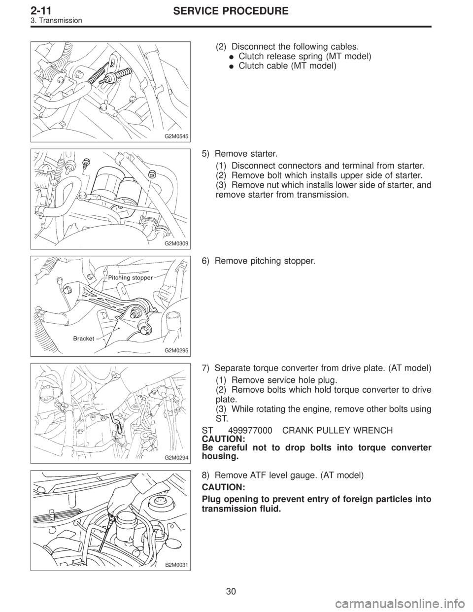
G2M0545
(2) Disconnect the following cables.
�Clutch release spring (MT model)
�Clutch cable (MT model)
G2M0309
5) Remove starter.
(1) Disconnect connectors and terminal from starter.
(2) Remove bolt which installs upper side of starter.
(3) Remove nut which installs lower side of starter, and
remove starter from transmission.
G2M0295
6) Remove pitching stopper.
G2M0294
7) Separate torque converter from drive plate. (AT model)
(1) Remove service hole plug.
(2) Remove bolts which hold torque converter to drive
plate.
(3) While rotating the engine, remove other bolts using
ST.
ST 499977000 CRANK PULLEY WRENCH
CAUTION:
Be careful not to drop bolts into torque converter
housing.
B2M0031
8) Remove ATF level gauge. (AT model)
CAUTION:
Plug opening to prevent entry of foreign particles into
transmission fluid.
30
2-11SERVICE PROCEDURE
3. Transmission
Page 829 of 2890

Automatic
transmis-
sionOil pumpType Variable-capacity type vane pump
Driving method Driven by engine
Number of vanes 9 pieces
Hydraulic
controlTypeElectronic/hydraulic control
[Four forward speed changes by
electrical signals of car speed and
accelerator (throttle) opening]
FluidDexron II or Dexron III type Automatic
transmission fluid
Fluid capacity2200 cc 7.9�(8.4 US qt, 7.0 Imp qt)
2500 cc 9.5�(10.0 US qt, 8.4 Imp qt)
LubricationLubrication system Forced feed lubrication with oil pump
OilAutomatic transmission fluid (above
mentioned.)
Cooling Cooling systemLiquid-cooled cooler incorporated in
radiator
HarnessInhibitor switch 12 poles
Transmission harnessFWD ... 11 poles
AWD ... 13 poles
TransferTransfer clutch Hydraulic multi-plate clutch
Clutch number of transfer clutchDrive plate &
driven plate5
Control method Electronic, hydraulic type
LubricantThe same Automatic Transmission
Fluid used in automatic transmission.
1st reduction gear ratio 1.000 (53/53)
Final
reductionFinal gear
ratioFront driveFWD 3.900 (39/10)
AWD2200 cc 4.111 (37/9)
2500 cc 4.444 (40/9)
Speedometer gear ratio2200 cc & 2500 cc 0.83 (19/23)
2500 cc OUTBACK 0.76 (19/25)
Lubrication oilAPI, GL-5
Oil
capacityFront drive 1.2�(1.3 US qt, 1.1 Imp qt)
AT F
cooling
systemRadiation capacity 1.651 kW (1,420 kcal/h, 5,635 BTU/h)
3
3-2SPECIFICATIONS AND SERVICE DATA
1. Automatic Transmission and Differential
Page 834 of 2890
D: FLUID PASSAGES
G3M0776
8
3-2SPECIFICATIONS AND SERVICE DATA
1. Automatic Transmission and Differential

-
WIRING
DIAGRAM
:
a
c
:
B5")
 Facing wear
Measure the depth of rivet head from the surface of facing.
Replace if facings are worn locally or worn down to less
than the specified value.
Depth")
 Facing wear
Measure the depth of rivet head from the surface of facing.
Replace if facings are worn locally or worn down to less
than the specified value.
Depth")