Page 52 of 2890
![SUBARU LEGACY 1996 Service Repair Manual
ON-BOARD
DIAGNOSTICS
II
SYSTEM
[T3C61]
2-7
3
.
Diagnosis
System
LED
No
.
Signal
name
Display
1
FWD
switch
FF
2
Kick-down
switch
KD
3
-
-
4
-
-
5
Brake
switch
BR
6
ABS
switch
AB
7
Cruise
cont SUBARU LEGACY 1996 Service Repair Manual
ON-BOARD
DIAGNOSTICS
II
SYSTEM
[T3C61]
2-7
3
.
Diagnosis
System
LED
No
.
Signal
name
Display
1
FWD
switch
FF
2
Kick-down
switch
KD
3
-
-
4
-
-
5
Brake
switch
BR
6
ABS
switch
AB
7
Cruise
cont](/manual-img/17/57433/w960_57433-51.png)
ON-BOARD
DIAGNOSTICS
II
SYSTEM
[T3C61]
2-7
3
.
Diagnosis
System
LED
No
.
Signal
name
Display
1
FWD
switch
FF
2
Kick-down
switch
KD
3
-
-
4
-
-
5
Brake
switch
BR
6
ABS
switch
AB
7
Cruise
control
set
CR
8
Power
switch
PW
9
--
-
I
10
-
I
-
FF
KD
--
BR
ABCR
PW
--
10
LEDNo
.
Signal
name
Display
1
N/P
range
switch
NP
2
R
range
switch
RR
3
D
range
switch
RD
43
range
switch
R3
52
range
switch
R2
6
1
range
switch
R1
7
Diagnosis
switch
SS
s
--
s
-
-
10
-
-
NPRRRDR3
R2
R1
SS
---
oaaoo
0000
,o
60
.
FUNCTION
MODE
:
FAO
-
ON
H
OFF
SIGNAL
-
Requirement
for
LED
"ON"
.
LED
No
.
1
Fuse
is
installed
in
FWD
switch
.
LED
No
.
2
Kick-down
switch
is
turned
ON
.
(Not
equipped)
LED
No
.
5
Brake
pedal
is
depressed
.
LED
No
.
6
ABS
signal
is
entered
.
LED
No
.
7
Cruise
control
is
set
.
LED
No
.
8
Power
switch
is
turned
ON
.
(Not
equipped)
61
.
FUNCTION
MODE
:
FA1
-
ON
H
OFF
SIGNAL
-
Requirement
for
LED
"ON"
.
LED
No
.
1
"N"
or
"P"
range
is
selected
.
LED
No
.
2"R"
range
is
selected
.
LED
No
.
3
"D"
range
is
selected
.
LEDNo
.
4
"3"
range
is
selected
.
LEDNo
.
5
"2"
range
is
selected
.
LEDNo
.
6
"1"
range
is
selected
.
LEDNo
.
7
Diagnosis
connector
is
connected
.
37
Page 65 of 2890
2-7
[1'6a2]
ON-BOARD
DIAGNOSTICS
11
SYSTEM
6
.
Wiring
Diagram
and
Wiring
Harness
2
.
AT
CONTROL
SYSTEM
To
Power
Supply
Routing
FB-20
~
FB-4
FB-15
~
FB-22
~
FB-30
FUSE
Na
15
FUSE
No
.
l6
FUSENa
lG
FUSENo
.
l5
FUSE
Na
l2
F45
862
Stop
l
ight
switch
*i
:
With
cruise
control
Diagnosis
Diagnosis
D
terminal
connector
BBIB82
*
1
B65
m
'
B64
"'
E
3
Combination
meter
Speedometer
circuit
/---\
FWD
AT
OIL
TEMP
i
l0
:
a
i14
:
c
i2
837
(4
B39
BI2
B64
(B
I
SC
k)
B65
(B
I
8C
k)
12
12
34
I10
(L
f
ght
gray)
1
1
1
2
1
3
1
4
1
5
1
6
1
7
1
8T9
l
lO
l
ll
l
l2
l
l3
l
l
-
4Fl5TI6
Ref
.
to
Back-up
)light
system
.
)Ref
.to
Starting
system
.
882
(B
I
ac
k)
(Gray)
B12
B21
(L
i
ght
gray)
i
14
1234
1
2
5678
1
3
1
4
1S1
6
9101112
1
1
1
2
1
3
1
4
1
5
1
6
M78
9
1
10
1
11
1
12
1
1
F45
(4
(B
I
ue)
t2
234
67
9
12345
6789(0
1111213141516171A19201~
111213141516171619202122
BUR41-02A
54
Inhibitor
switch
Page 66 of 2890

ON-BOARD
DIAGNOSTICS
II
SYSTEM
[Tsn2i
2-7
6
.
Wiring
Diagram
and
Wiring
Harness
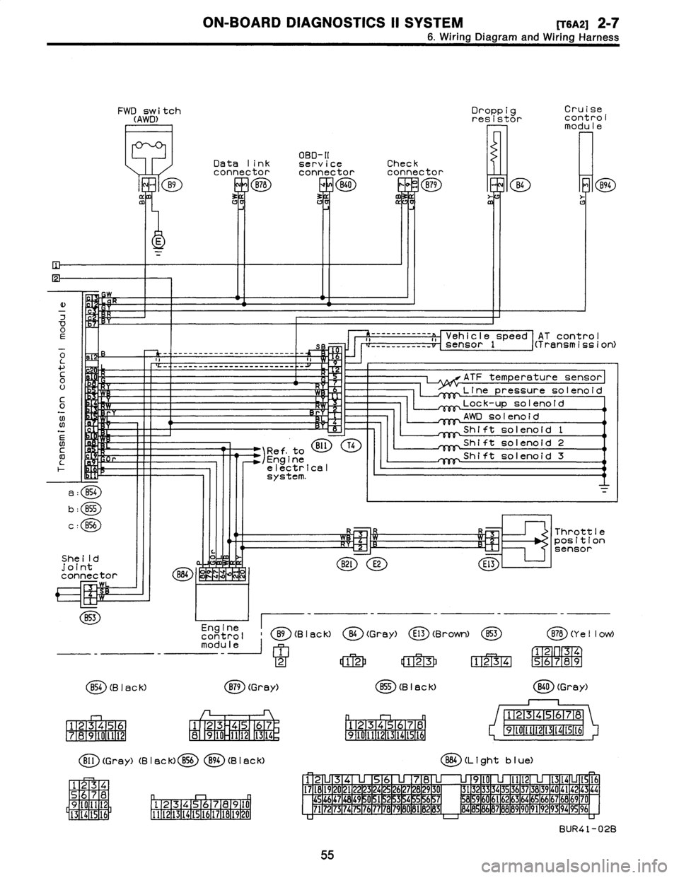
FWD
switch
(AWD)
B9
ffl
Droppig
Cruise
resistor
cont
rol
modu
le
OBD-II
Data
link
serviceCheck
connectorconnectorconnector
B78
ERB40
0
B79
m
B4
E
K
E
)
w
7
OEs
o
-
-
-
------------------
-
------
-
-
L
a
....
c
H
0
U
It
C
Y
0
.N
;W
Rr
06
N
BI1
T41
Ref
.
to
/Engine
electrical
system
.
a
:
B54
b
:
B55
c
:
856
She
ild
joint
connector
884
~
WK
LZIM
WL
B53
Engine
control
B9(B
I
ac
k)
module
1
2
854
(B
I
ac
k)
B79
(Grey)
1
23456
1
23
45
67
7
1
8
1
9101112
8
910
1112
1
13
1
14
r,
Bll
(Grey)
(B
I
ac
k)
B56894
(B
I
aCk)
34
S
78
D
q
Oil
2
9
Pl
.
12131415,91617
la19
110
I
5
16
1
3
14
1111121131141151161171161191201
AT
contro
I
------------
a
,,
Vehicle
speed
i(Transmission)
___
_____
__
__
sensor
1
ATF
temperature
sensor
Line
pressuresolenoid
Lock-up
solenoid
AWD
solenoid
Shift
solenoid
1
Shift
solenoid
2
Shift
solenoid
3
R3
Throttle
~-Cz'1
R~l
position
sensor
B2l
E2
El3
O
(Gray)
E13
(Brown)
853
B78
(Y
e
II
ow)
12
123
1234
56789
B55
(B
I
ack)
(
ED
(Grey)
12345678
12345678
9~011t213141St6
91111213141516
864
(L
i
ght
b
I
ue)
12
345678
9l0
lll21314
1516
I7l8l9
20
2122
23
24
2627282930
3132
3334
35
3637383940
4142
43
44
454647
1
48
1
49
~
0
1
51
2
15
3
15
4
~
5
1
56
15
7
8596061626364656667686970
7172
73
1
74
1
75
1
76
1
77
78
1
79
1
60
1
81
B
1
132
1
83d
8485
86
87888990
9192
93
94
9596
BUR41-02B
55
Page 86 of 2890

ON-BOARD
DIAGNOSTICS
11
SYSTEM
[T11aoj
2-7
11
.
Diagnostics
Chart
with
Trouble
Code
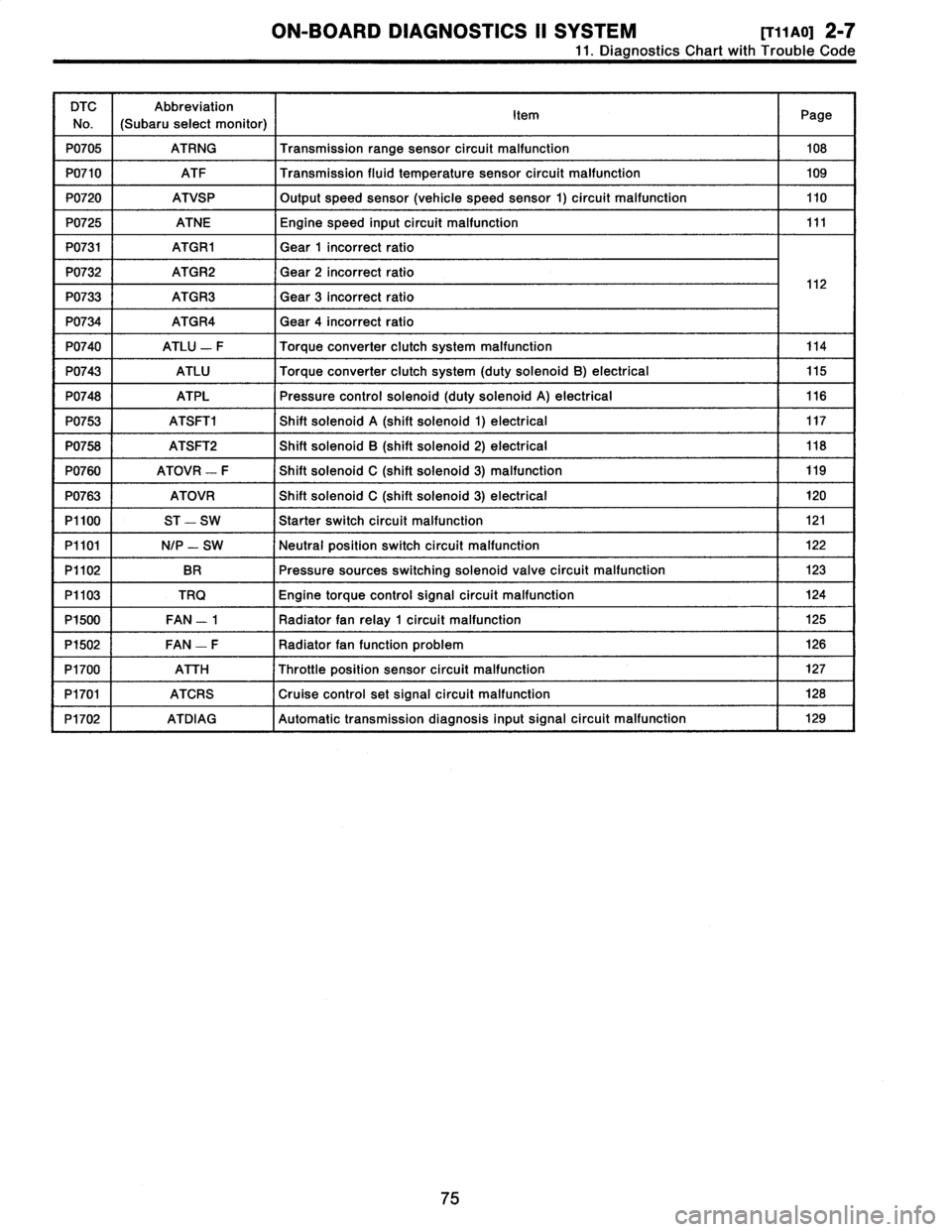
DTC
No
.
Abbreviation
(Subaru
select
monitor)
Item
Page
P0705
ATRNG
Transmissionrange
sensor
circuit
malfunction
108
P0710
ATF
Transmission
fluid
temperature
sensor
circuit
malfunction
109
P0720
ATVSP
Output
speed
sensor
(vehicle
speed
sensor
1)
circuit
malfunction
110
P0725
ATNE
Engine
speed
input
circuit
malfunction
111
P0731
ATGR1
Gear
1
incorrect
ratio
P0732
ATGR2
Gear
2
incorrect
ratio
1
2
P0733
ATGR3
Gear
3
incorrect
ratio
1
P0734
ATGR4
Gear
4
incorrect
ratio
P0740
ATLU
-
F
Torque
converter
clutch
system
malfunction
114
P0743
ATLU
Torque
converter
clutch
system
(duty
solenoid
B)
electrical
115
P0748
ATPL
Pressure
control
solenoid
(duty
solenoid
A)
electrical
116
P0753
ATSFTi
Shift
solenoid
A
(shift
solenoid
1)
electrical
117
P0758
ATSFT2
Shift
solenoid
B
(shift
solenoid
2)
electrical
118
P0760
ATOVR
-
F
Shift
solenoid
C
(shift
solenoid
3)
malfunction
119
P0763
ATOVR
Shift
solenoid
C
(shift
solenoid
3)
electrical
120
P1100
ST
-
SW
Starter
switch
circuit
malfunction
121
P1101
N/P
-
SW
Neutral
position
switch
circuit
malfunction
122
P1102
BR
Pressure
sources
switching
solenoid
valve
circuit
malfunction
123
P1103
TRQ
Engine
torque
control
signal
circuit
malfunction
124
P1500
FAN
-
1
Radiator
fan
relay
1
circuit
malfunction
125
P1502
FAN
-
F
Radiator
fan
function
problem
126
P1700
ATTH
Throttle
position
sensor
circuit
malfunction
127
P1701
ATCRS
Cruise
control
set
signal
circuit
malfunction
128
P1702
ATDIAG
Automatic
transmission
diagnosis
inputsignal
circuit
malfunction
I
129
75
Page 118 of 2890
ON-BOARD
DIAGNOSTICS
II
SYSTEM
[T11AM0]
2-7
11
.
Diagnostics
Chart
with
Trouble
Code
AM
:
DTC
P0703
-
BRAKE
SWITCH
INPUT
MALFUNCTION
(ATBRK)
-
WIRING
DIAGRAM
:
BS6
No
.
12
SBF-3
FL
1
.
25BTCM
7
-
II
u
B64
*
1
:
Bb5
Tostoplights
I
*1
:
With
cruise
control
00
Brake
light
switch
856
B64865
12345678910
12
11121314151617181920
1
2
34
1321V10905
NOTE
:
For
the
diagnostic
procedure
on
brake
switch
input
mal-
function
(DTC
P0703),
referto
2-7
[T10AM0]*2
.
107
Page 139 of 2890
2-7
[T11BJ0]
ON-BOARD
DIAGNOSTICS
II
SYSTEM
11
.
Diagnostics
Chart
with
Trouble
Code
BJ
:
DTC
P1701
-
CRUISE
CONTROL
SET
SIGNAL
CIRCUIT
MALFUNCTION
(ATCRS)
-
WIRING
DIAGRAM
:
896
TCM
_1
a
:
CCM
U
B56
896
123456789(0
11121314(516Ut819
0
OBD0512
NOTE
:
For
the
diagnostic
procedure
on
cruise
control
set
signal
circuit
malfunction
(DTC
P1701),
refer
to
2-7
[T10BL0]*2
.
128
Page 175 of 2890
![SUBARU LEGACY 1996 Service Repair Manual
s-$
[D601]
WIRING
DIAGRAM
6
.
Wiring
Diagram
No
.
Load
MB-2
Powerwindow
circuit
breaker
Engine
control
module
Fuel
pump
relay
MB-3
Main
relay
OBD-II
service
connector
MB-4A/C
relay
holder
MB- SUBARU LEGACY 1996 Service Repair Manual
s-$
[D601]
WIRING
DIAGRAM
6
.
Wiring
Diagram
No
.
Load
MB-2
Powerwindow
circuit
breaker
Engine
control
module
Fuel
pump
relay
MB-3
Main
relay
OBD-II
service
connector
MB-4A/C
relay
holder
MB-](/manual-img/17/57433/w960_57433-174.png)
s-$
[D601]
WIRING
DIAGRAM
6
.
Wiring
Diagram
No
.
Load
MB-2
Powerwindow
circuit
breaker
Engine
control
module
Fuel
pump
relay
MB-3
Main
relay
OBD-II
service
connector
MB-4A/C
relay
holder
MB-6
Headlight
LH
Diode
(Lighting)
Lighting
switch
Combination
meter
M
B_$
Headlight
RH
Combination
meter
Door
lock
timer
MB-9
Luggage
room
light
Radio
Room
light
MB-10
A/C
relay
holder
ALT-1
Combination
meter
IG
A/C
relay
holder
Cruise
control
module
ST
Engine
control
module
Inhibitor
switch
FB-2
Diode
(A/C)
Sub
fan
motor
FB-3
Sub
fan
relay-2
Engine
control
module
Fuel
pump
relay
FB-4
Ignition
coil
Transmission
control
module
Side
marker
light
LH
FB-6
Side
marker
light
RH
FB-7Door
lock
timer
FB-9Hazard
switch
AT
shift
lock
control
module
FB-10
Key
warning
switch
Power
antenna
FB-11
Radio
FB-12
Cigarette
lighter
FB-13
Remote
control
rearview
mirrorswitch
AT
shift
lock
control
module
Combination
switch
Front
washer
motor
FB-14
Front
wipermotor
Rear
washer
motor
Rear
wipermotor
Rear
wiper
relay
FB-15Transmission
control
module
Na
Load
Rear
defogger
FB-16
Rear
defogger
condenser
Reardefogger
switch
FB-17
Rear
defogger
switch
FB-18
AT
shift
lock
control
module
Inhibitor
switch
FB-19
Hazard
switch
Combination
meter
FB-20
Mode
control
panel
FB-21
Combination
meter
(Airbag)
Blower
motor
relay
Check
connector
FB-22
FRESH/RECIRC
actuator
Mode
actuator
Powerwindow
relay
Seat
belt
timer
FB-23
Airbag
.
control
module
FB-24
Airbag
control
module
FB-25
Lighting
switch
FB-26
Parking
switch
FB-27
Parking
switch
FB-28
Illumination
light
FB-29
Illumination
light
FB-30
Stop
light
switch
Stop
&
brake
switch
FB-31
Horn
relay
FB-32
Blower
motor
relay
FB-33
Parking
switch
License
plate
light
LH
License
plate
light
RH
FB-34
Rear
combination
light
LH
Rear
combination
light
RH
Rear
finisher
light
LH
Rear
finisher
light
RH
FB-35
Cruise
control
main
switch
Cruise
control
module
Page 176 of 2890

6-3
[0602
WIRING
DIAGRAM
6
.
Wiring
Diagram
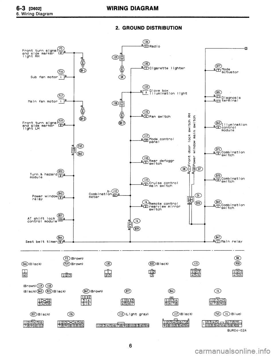
2
.
GROUND
DISTRIBUTION
i26
RedioFront
turn
signal
F3
end
side
marker
rm
light
RH
i
i29
i25
~~--
--
a
--~~
Cigarette
lighter
sB77
Mode
F16
~-~
E
I
actuator
Subfan
motor
i
O
Main
fan
motor
Front
turn
signs
Dend
side
marker
123-1
light
LH
832
Turn
&hazardmodule
Power
wi
relay
AT
shift
lock
857
control
module
(28
:
E
GB-2
FGS
B62
b
:
ill
Combination
meter
(4
m
839
Seat
belt
t
i
mer
C',"-i
F3
(BrowN
O66
(B
I
BC
k)
F19
(Brown)
123
(Brown)
fig
118
(B
I
ac
k)
B43
R15
(B
I
ec
k)
1
2
1
3
1
4
151
6
i
25
1
23
i23
rGlove
box
L~
Illum(nation
light
Fan
switch
L
!-
+'
3
N
NC
i
l7'Z
00
Mode
control
o
panel
0o
~c
'0o
3
il8
4-
L
3
Rear
defoggr
~
o3
switch
O
~m~
07
m
119
Cruise
control
mainswitch
G)§emote
ontro
I
c
LM
rearv
i
e
irror
switch
(g)
(B
I
ec
k)
CD
1
23
4
M
S6
(g)(Brown)
(~D
1
23
[96
R4
;6R7
(~D(BISCK)
(~D
ff~
1516-111
12131><14151
111213
171a191101111121
1718191101111121131141
CD
(L
(ght
gray)
4
'
:F
151617
P911011111~~
D
I
agnos
1
s
Lrm
term
1
na
I
(E~)l
II
um
I
nat
1
on
LEE
contro
I
modu
I
e
(ED
LM
Combination
switch
870
sl=
Combination
switch
B69
Combination
switch
867
-IM
Main
relay
141516
(E)
(a)
1
234
S6JR8
161
r
1
E319
1101
(aD
(B
I
ac
K)
(B
I
u
e)
p
r-1
n
~1
1
F2-1[3
1
f41516
1
7a
0
1
2-
F
-
1q,
[3
46
112-2TI-3114115116117118119120
I'F
BUR04-02A
6