Page 727 of 2890
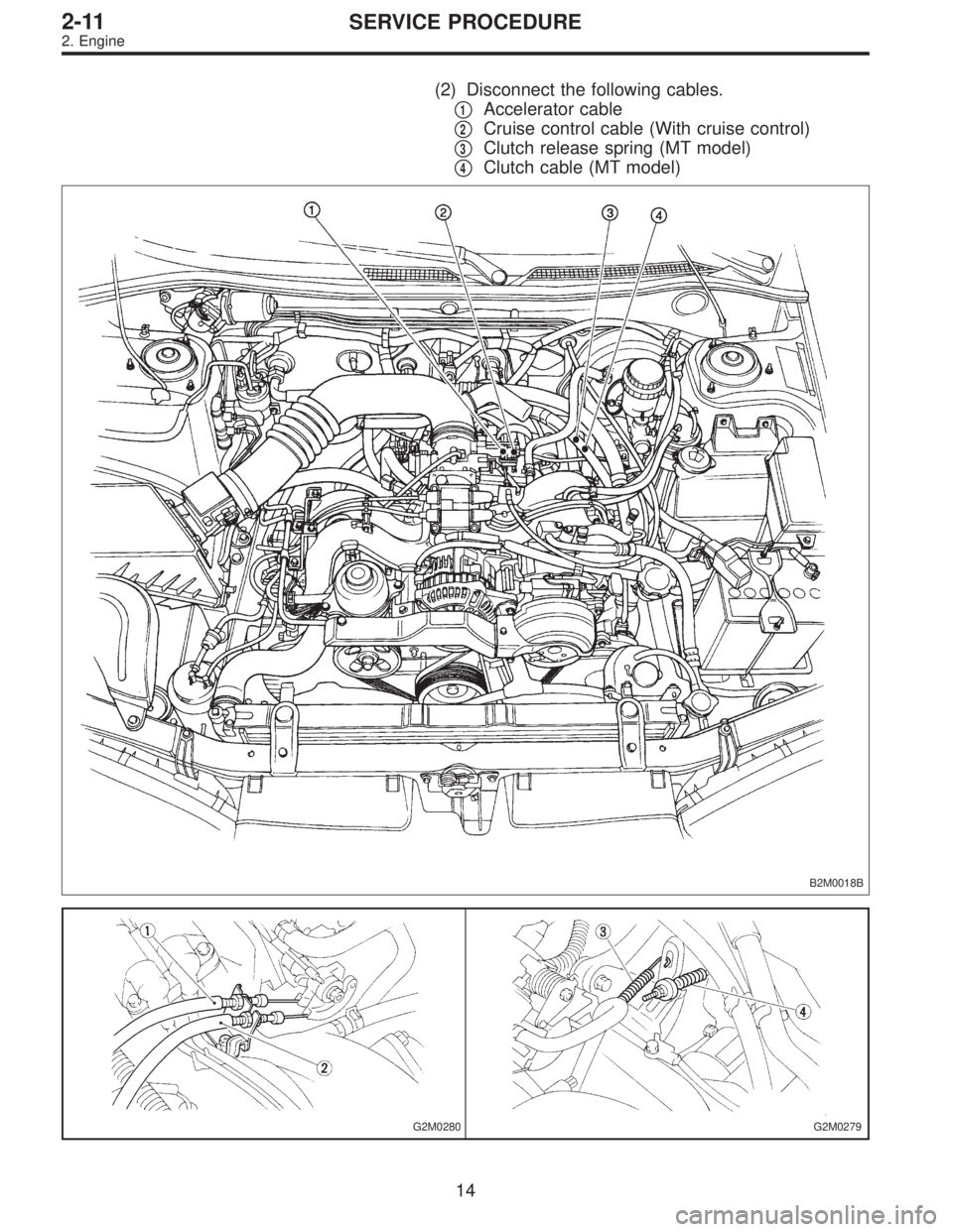
(2) Disconnect the following cables.
�
1Accelerator cable
�
2Cruise control cable (With cruise control)
�
3Clutch release spring (MT model)
�
4Clutch cable (MT model)
B2M0018B
G2M0280G2M0279
14
2-11SERVICE PROCEDURE
2. Engine
Page 737 of 2890
11) Install front exhaust pipe and center exhaust pipe.
12) Connect hoses, connectors and cables.
(1) Connect the following hoses.
�Fuel delivery hose, return hose and evaporation
hose
�Heater inlet and outlet hoses
�Brake booster vacuum hose
(2) Connect the following connectors.
�Engine ground terminal
�Engine harness connectors
�Front oxygen sensor connector
�Rear oxygen sensor connector
�Alternator connector and terminal
�A/C compressor connectors (With A/C)
(3) Connect the following cables.
�Accelerator cable
�Cruise control cables (With cruise control)
�Clutch cable
�Clutch release spring
CAUTION:
After connecting each cable, adjust them.
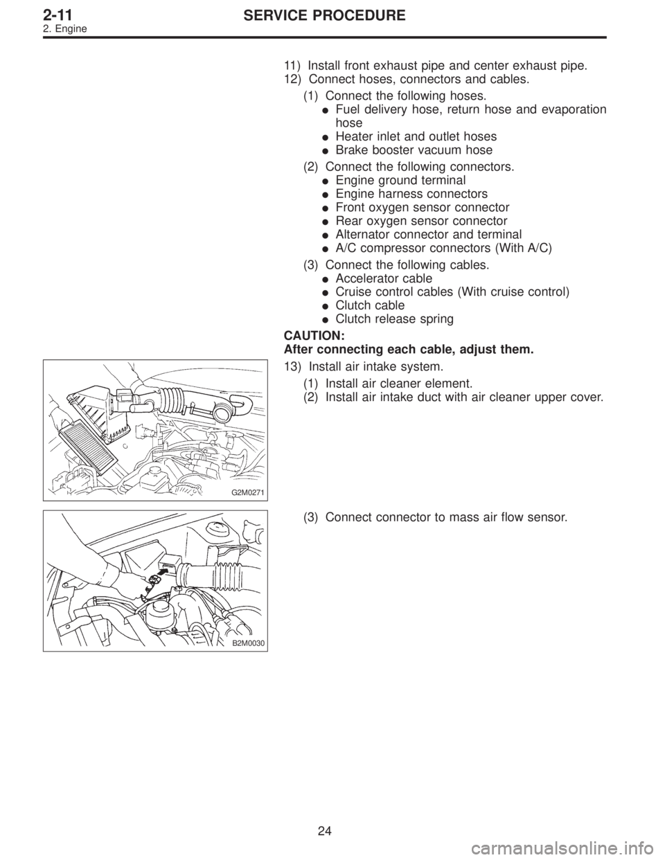
G2M0271
13) Install air intake system.
(1) Install air cleaner element.
(2) Install air intake duct with air cleaner upper cover.
B2M0030
(3) Connect connector to mass air flow sensor.
24
2-11SERVICE PROCEDURE
2. Engine
Page 756 of 2890
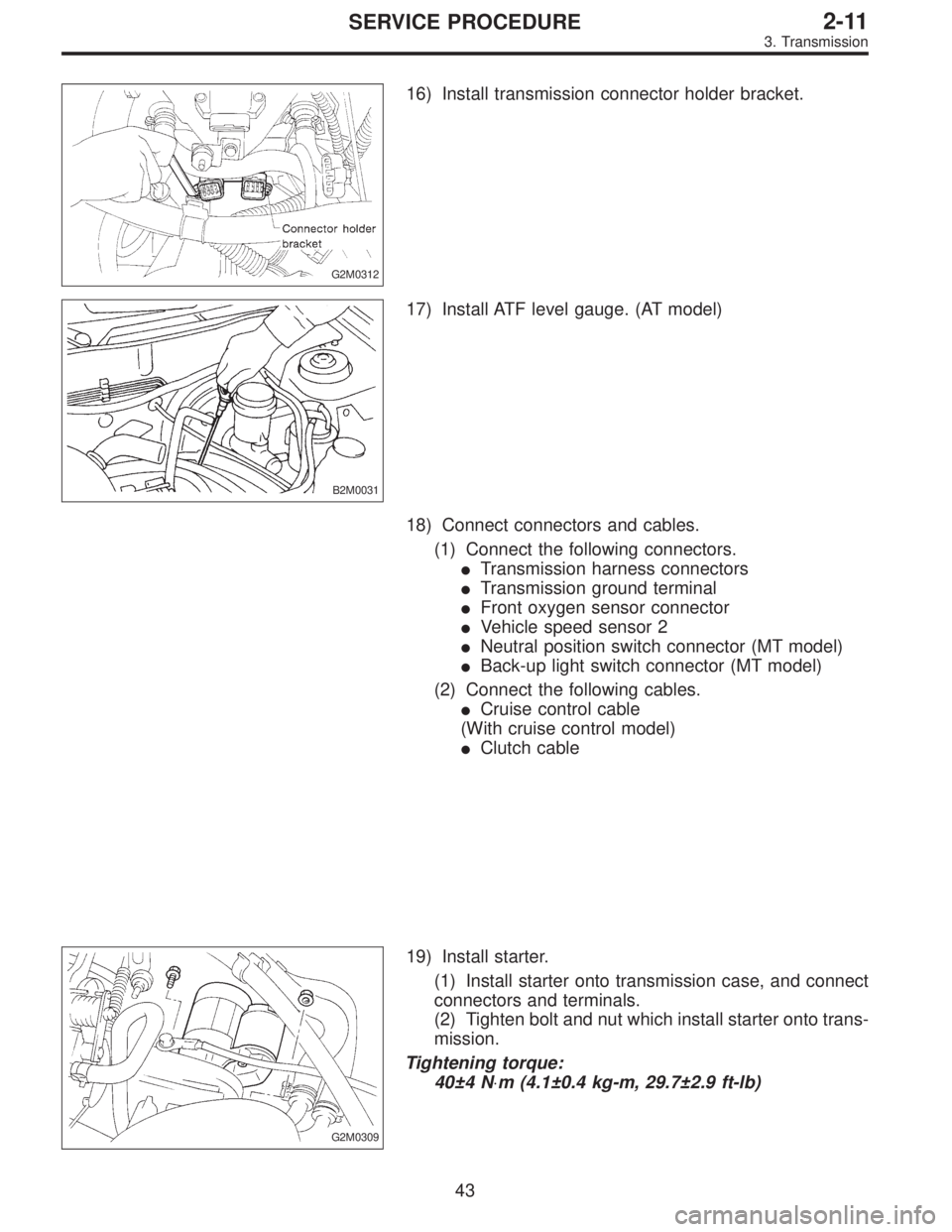
G2M0312
16) Install transmission connector holder bracket.
B2M0031
17) Install ATF level gauge. (AT model)
18) Connect connectors and cables.
(1) Connect the following connectors.
�Transmission harness connectors
�Transmission ground terminal
�Front oxygen sensor connector
�Vehicle speed sensor 2
�Neutral position switch connector (MT model)
�Back-up light switch connector (MT model)
(2) Connect the following cables.
�Cruise control cable
(With cruise control model)
�Clutch cable
G2M0309
19) Install starter.
(1) Install starter onto transmission case, and connect
connectors and terminals.
(2) Tighten bolt and nut which install starter onto trans-
mission.
Tightening torque:
40±4 N⋅m (4.1±0.4 kg-m, 29.7±2.9 ft-lb)
43
2-11SERVICE PROCEDURE
3. Transmission
Page 943 of 2890
G6M0095
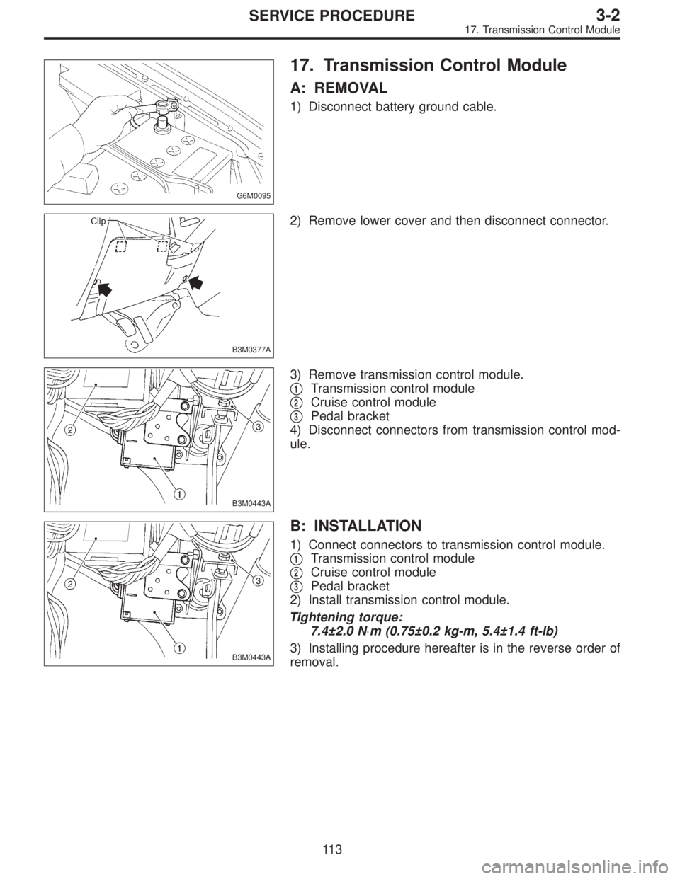
17. Transmission Control Module
A: REMOVAL
1) Disconnect battery ground cable.
B3M0377A
2) Remove lower cover and then disconnect connector.
B3M0443A
3) Remove transmission control module.
�
1Transmission control module
�
2Cruise control module
�
3Pedal bracket
4) Disconnect connectors from transmission control mod-
ule.
B3M0443A
B: INSTALLATION
1) Connect connectors to transmission control module.
�
1Transmission control module
�
2Cruise control module
�
3Pedal bracket
2) Install transmission control module.
Tightening torque:
7.4±2.0 N⋅m (0.75±0.2 kg-m, 5.4±1.4 ft-lb)
3) Installing procedure hereafter is in the reverse order of
removal.
11 3
3-2SERVICE PROCEDURE
17. Transmission Control Module
Page 1121 of 2890
G5M0328
6) Align center of roll connector. (with airbag model)
CAUTION:
Ensure that front wheels are set in straight-forward
direction.
7) Set steering wheel to neutral and install it onto steering
shaft.
Tightening torque:
34±5 N⋅m (3.5±0.5 kg-m, 25.3±3.6 ft-lb)
Column cover-to-steering wheel clearance:
2 — 4 mm (0.08 — 0.16 in)
CAUTION:
Insert roll connector guide pin into guide hole on lower
end of surface of steering wheel to prevent damage.
Draw out airbag system connector, horn connector
and cruise control connectors from guide hole of
steering wheel lower end. (with airbag model)
8) Install airbag module to steering wheel. (with airbag
model)
WARNING:
Always refer to 5-5 [W3B1] before performing the ser-
vice operation.
14
4-3SERVICE PROCEDURE
2. Tilt Steering Column
Page 1173 of 2890
G4M0167
11) Finally check clearance between pipes and/or hoses,
as shown above.
If clearance between cruise control pump and power steer-
ing hose is less than 10 mm (0.39 in), proceed as follows:
(1) Move clamped section�
A(refer to figure above.)
down to a point where pipe is close to crossmember.
Pipe-to-crossmember clearance:
10 mm (0.39 in), min.
(2) Check that clearance between cruise control pump
and power steering hose is at least 10 mm (0.39 in). If
it is not, bend section�
Bdown until a clearance of at
least 10 mm (0.39 in) is obtained.
66
4-3SERVICE PROCEDURE
7. Pipe Assembly (Power Steering System) [LHD model]
Page 1204 of 2890
7. CLEARANCE TABLE (LHD MODEL)
CAUTION:
This table lists various clearances that must be cor-
rectly adjusted to ensure normal vehicle driving with-
out interfering noise, or any other faults.
LocationMinimum
allowance
mm (in)LocationMinimum
allowance
mm (in)
�
1Crossmember—Pipe5 (0.20)�6Exhaust pipe—Pipe15 (0.59)
�
2DOJ—Shaft or joint14 (0.55)�7Exhaust pipe—Gearbox bolt15 (0.59)
�
3DOJ—Valve housing11 (0.43)�8Side frame—Hose A and B15 (0.59)
�
4Pipe—Pipe
2 (0.08)�
9Cruise control pump—Hose A and B15 (0.59)
Pipe—Crossmember�
10Pipe portion of hose A—Pipe portion of hose B1.5
(0.059)
�
5Stabilizer—Pipe5 (0.20)�11AT cooling hose—Joint20 (0.79)
B4M0565A
97
4-3DIAGNOSTICS
1. Power Steering
Page 1339 of 2890
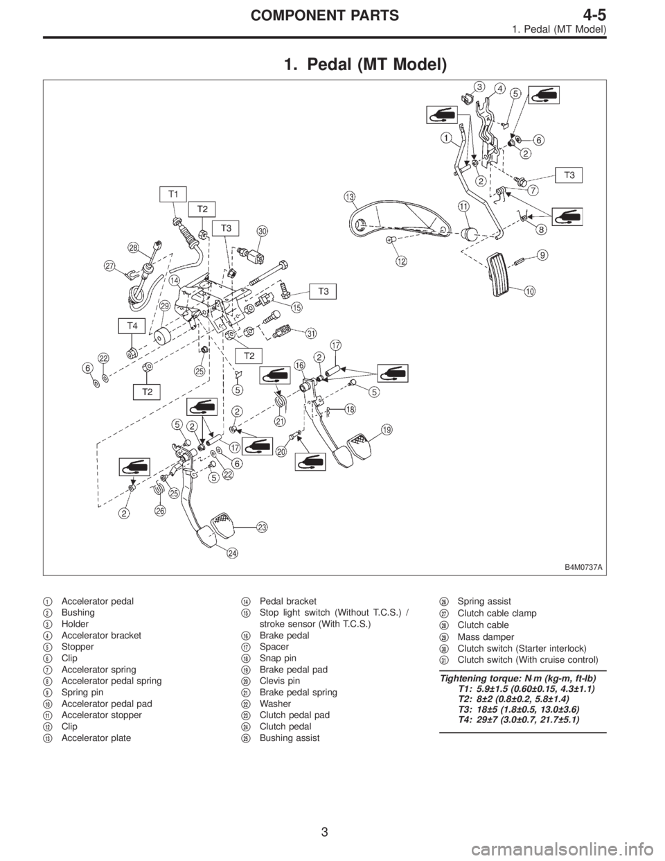
1. Pedal (MT Model)
B4M0737A
�1Accelerator pedal
�
2Bushing
�
3Holder
�
4Accelerator bracket
�
5Stopper
�
6Clip
�
7Accelerator spring
�
8Accelerator pedal spring
�
9Spring pin
�
10Accelerator pedal pad
�
11Accelerator stopper
�
12Clip
�
13Accelerator plate�
14Pedal bracket
�
15Stop light switch (Without T.C.S.) /
stroke sensor (With T.C.S.)
�
16Brake pedal
�
17Spacer
�
18Snap pin
�
19Brake pedal pad
�
20Clevis pin
�
21Brake pedal spring
�
22Washer
�
23Clutch pedal pad
�
24Clutch pedal
�
25Bushing assist�
26Spring assist
�
27Clutch cable clamp
�
28Clutch cable
�
29Mass damper
�
30Clutch switch (Starter interlock)
�
31Clutch switch (With cruise control)
Tightening torque: N⋅m (kg-m, ft-lb)
T1: 5.9±1.5 (0.60±0.15, 4.3±1.1)
T2: 8±2 (0.8±0.2, 5.8±1.4)
T3: 18±5 (1.8±0.5, 13.0±3.6)
T4: 29±7 (3.0±0.7, 21.7±5.1)
3
4-5COMPONENT PARTS
1. Pedal (MT Model)
![SUBARU LEGACY 1996 Service Repair Manual G5M0328
6) Align center of roll connector. (with airbag model)
<Ref. to 5-5 [W7B1].>
CAUTION:
Ensure that front wheels are set in straight-forward
direction.
7) Set steering wheel to neutral and insta](/manual-img/17/57433/w960_57433-1120.png "SUBARU LEGACY 1996 Service Repair Manual G5M0328
6) Align center of roll connector. (with airbag model)
<Ref. to 5-5 [W7B1].>
CAUTION:
Ensure that front wheels are set in straight-forward
direction.
7) Set steering wheel to neutral and insta")
 Finally check clearance between pipes and/or hoses,
as shown above.
If clearance between cruise control pump and power steer-
ing hose is less than 10 mm (0.39 in), proceed as follows:
(1)")

CAUTION:
This table lists various clearances that must be cor-
rectly adjusted to ensure normal vehicle driving with-
out interfering noise, or any other faults.
Locatio")