1996 SUBARU LEGACY cruise control
[x] Cancel search: cruise controlPage 177 of 2890
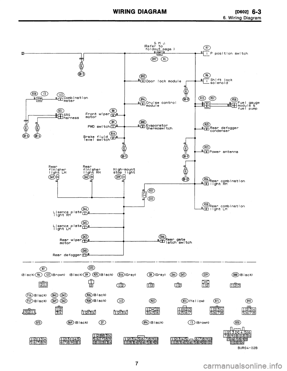
WIRING
DIAGRAM
[oso2i
6-3
6
.
Wiring
Diagram
GB-3
838
13
i13
s-r,
Comb
inationmeter
831
O
SRS
Front
wiper
cui
harness
motor
B9
E
E
FWD
switchCIll
GB-6
GB-4
Brake
fluid
B
CE
level
switch
S
.
M
.
J
.
(Refer
to
foldout
page
.]
B97
Rl
892
IM
Door
lock
module
R7
-71P
position
switch
i
Shift
lock
-
solenoid
B94
~
R~5
R57
RSB
Cruise
control
Fuel
gauge
modulemodule
&
fuel
pump
Evaporator
~z
thermoswltch
Rear
defogger
condenser
R23
-
e
Power
antenna
GB-5GB-9
Rear
Rearfinisher
finisher
High-mount
light
LH
light
RHStop
light
D69042D39
-
~-l
R26
car
combination
m
light
RH
R37
m4
0~3
Lisence
plat
044
e
light
RH
D45
Llsence
plate
light
LH
043
Rear
wtperEnj
motor
D4B
Rear
defogge
r
D46
Reargete
latch
switch
tear
combination
light
LH
-
-
-
-
-
-
-
-
-
-
-
-
-
-
-
-
R7
D33
(Black)
R6
i23
(Brown)(Black)
B9
O(Black)
816
(G
rey)
O(Gray)
DL4D65X39
88B
(B18ck)
21
2
12
12
1212
123
Flb
(B
I
ac
k)
B62D63R26
(B
I
8C
k)
F17
(g
I
flc
k)
DG9042R2B
(B
I
ac
k)
i
13
R23
X31
(Ye
II
ow)
(E)
1
2
34
riT2
ri-r2
m34
131415161
o23
R45
67
1
234
1
234
S
M67
8
P567
N8
(B
I
ac
k)
07
894
(B
I
ac
k)i3
(Brown)
830
1
2
34
1
23
4
67
89
1
12
4
78910
1
1
7891
7
23
L
5
16
89
2211171
4
112131
19
0
6
141
6789
67891
1
1
112(3(
111
l
141
1617LB19
t
12114
1
1611
192
p1
BUR04-02B
7
Page 180 of 2890
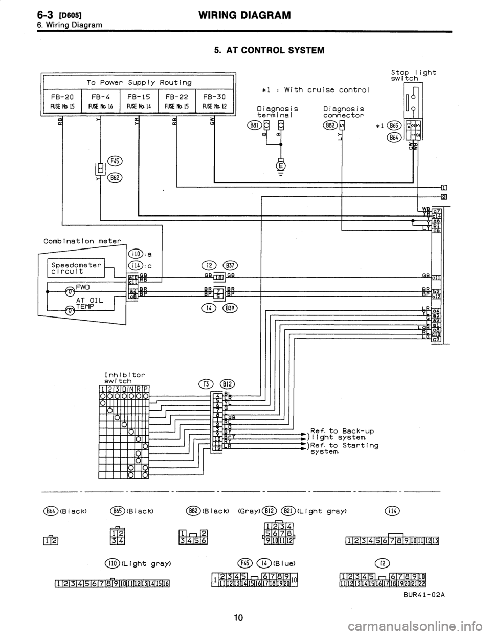
6-3
[osos1
WIRING
DIAGRAM
6
.
Wiring
Diagram
5
.
AT
CONTROL
SYSTEM
To
Power
Supply
Routing
FB-20
FUSE
Na
15
FB-4
~
FUSENo
.
l6
FB-15
~
FUSE
Na
l4
FB-22
FUSE
Na
LS
FB-30
FUSE
Na
t2
F45
862
Combination
meter
Speedometer
circuit
/--\
FWD
AT
OIL
TEMP
i2837
i(0
:
g
C14
:
c
r4
B39
812
Stop
light
switch
*1
:
With
cruise
control
Diagnosis
Diagnosis
D
terminal
connector
B81
882
*
1
865
;,
m
E
'
B64
Ref
.
to
Back-up
)light
system
.
)Ref-to
Startingsystem
.
B64
(B
I
sC
k)
B65
(B
I
aC
k)
12
12
34
i
10
(L
i
ght
grey)
1234
678910111213(41516
2
5678
456
9101112
1
11213141516
78910111213
F45
14
(B
I
u
e)
i2
4
89
12
45
678910
1
1
11
1
1
21
15
1
14
1
1-511
36
1718714201
111213141516171814202122
BUR41-02A
892
(B
I
ac
k)
(Gray)
B12
B21
(L
i
ght
gray)
i
14
1234
10
Inhibitor
switch
Page 188 of 2890
cal
Wiring
Harness
and
Ground
Point
Connector
Connecting
to
Pole
Color
Area
No
.
Name
2
Brown
B-2
Pressure
sources
switching
solenoid
3
Black
B-2
Pressure
sensor
5
Gray
B-2
Mass
air
flow
sensor
2
Gray
B-2
AT
dropping
resistor
4
Gray
B-3
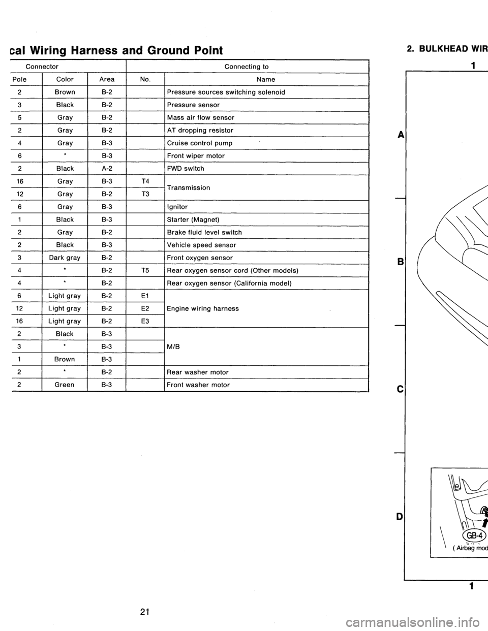
Cruise
control
pump
6B-3Front
wipermotor
2
Black
A-2
FWD
switch
16
Gray
B-3
T4
T
i
12
Gray
B-2
T3
ransmiss
on
6
Gray
B-3
Ignitor
1
Black
B-3
Starter
(Magnet)
2
Gray
B-2
Brake
fluid
level
switch
2
Black
B-3
Vehicle
speed
sensor
3
Dark
gray
B-2
Front
oxygen
sensor
4
B-2
T5
Rear
oxygen
sensor
cord
(Other
models)
4
B-2
Rear
oxygen
sensor
(California
model)
6Light
gray
B-2
E1
12Light
gray
B-2
E2Engine
wiring
harness
16Light
gray
B-2
E3
2
Back
B-3
3
B-3
MIB
1
Brown
B-3
2B-2
Rear
washer
motor
2f
Green
B-3Front
washer
motor
2
.
BULKHEAD
WIRING
HARNESS
AND
GROUND
POINT
(IN
ENGINE
ROOM)
2
I
a
B
C
-r
t
n
GB-4
GB-5
(
rbag
mode
)
B6M0086B
D
1
3
4
4
[D802]
B6M0587A
A
B
C
D
21
Page 189 of 2890
8
.
Electrical
Wiring
Harness
and
Ground
Point
Connector
Connecting
to
No
.
Pole
Color
Area
No
.
Name
131
2
Brown
B-2
Pressure
sources
switching
solenoid
B2
3
Black
B-2
Pressure
sensor
B3
5
Gray
B-2
Mass
air
slow
sensor
B4
2
Gray
B-2
AT
dropping
resistor
B7
4
Gray
B-3
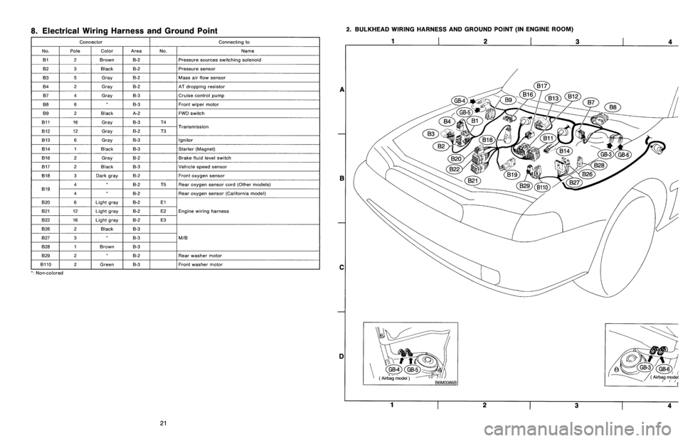
Cruise
control
pump
B8
6B-3Front
wiper
motor
B9
2
Black
A-2
FWD
switch
B11
16
Gray
B-3
T4
T
B12
12
Gray
B-2
T3
ransmission
B13
6
Gray
B-3
Ignitor
B14
1
Black
B-3
Starter
(Magnet)
B16
2
Gray
B-2
Brake
fluid
level
switch
B17
2
Black
B-3
Vehicle
speed
sensor
B18
3
Dark
gray
B-2Front
oxygen
sensor
4B-2
T5Rear
oxygen
sensor
cord(Other
models)
B19
4B-2
Rear
oxygen
sensor
(California
model)
B20
6Light
gray
B-2El
821
12
Light
gray
B-2
E2Engine
wiring
harness
B22
16
Light
gray
B-2
E3
B26
2
Black
B-3
B27
3B-3
MIB
B28
1
Brown
B-3
B29
2B-2
Rear
washer
motor
B110
~
2
f
Green
B-3
~
Front
washer
motor
`
:
Non-colored
2
.
BULKHEAD
WIRING
HARNESS
AND
GROUND
POINT
(IN
ENGINE
ROOM)
1
2
3
a
E
C
DI
Yi-t
~
GB-4GB-5
(Air
`bag
model
(
Airbag
model
~rrE
1
23
4
21
Page 190 of 2890
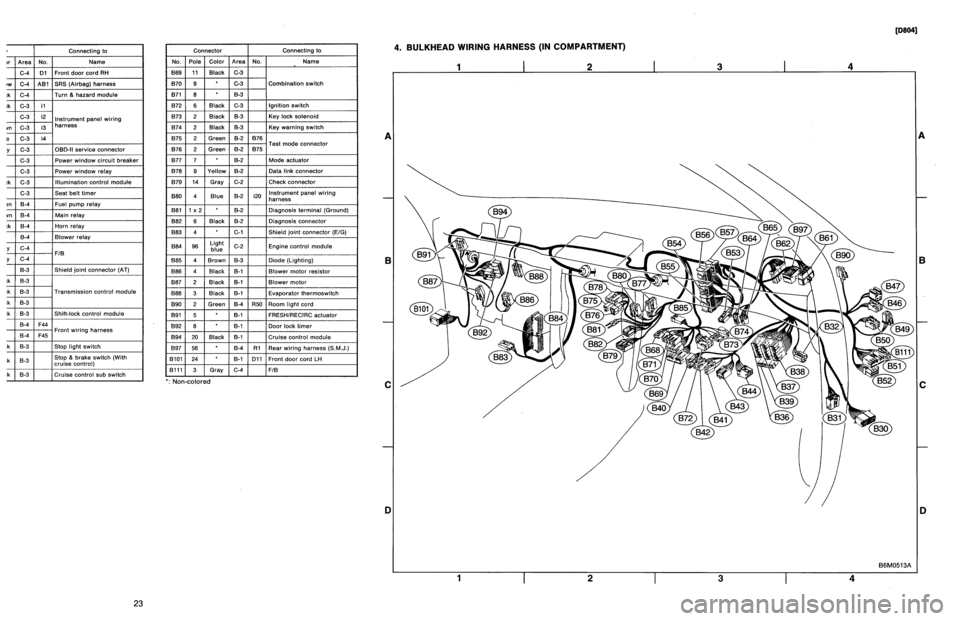
r
Connecting
to
)r
Area
No
.
Name
C-4
D1
Front
doorcord
RH
ow
C-4
ABi
SRS
(Airbag)
harness
;k
C-4
Turn
&
hazard
module
.k
C-3
i1
C-3
i2
instrument
panel
wiring
un
C-3
i3
harness
e
C-3
i4
y
C-3
OBD-IIservice
connector
C-3
Power
window
circuit
breaker
C-3
Power
window
relay
;k
C-3
Illuminationcontrol
module
C-3
Seat
belt
timer
;n
B-4
Fuel
pump
relay
vn
B-4
Main
relay
;k
B-4
Horn
relay
B-4
Blower
relay
y
C-4
FIB
y
C-4
B-3
Shield
joint
connector
(AT)
.k
B-3
:k
B-3
Transmission
control
module
.k
B-3
:k
B-3
Shift-lock
control
module
B-4F44
i
h
B-4F45
Front
w
ring
arness
.k
B-3
Stop
light
switch
,k
B-3
Stop
8
brake
switch
(Withcruise
control)
:k
8-3
Cruise
control
sub
switch
Connector
Connecting
to
No
.
Pole
Color
Area
No
.
Name
869
11
Black
C-3
B70
9
C-3
Combination
switch
B71
8
8-3
B72
6
Black
C-3
Ignition
switch
B73
2
Black
B-3
Key
lock
solenoid
B74
2
Black
B-3
Key
warning
switch
B75
2
Green
B-2
876
T
d
B76
2
Green
8-2
875
e
connector
est
mo
877
7
B-2
Mode
actuator
B78
9
Yellow
B-2
Data
link
connector
B79
14
Gray
C-2
Check
connector
BBO
4
Blue
B-2
i20
Instrument
panel
wiring
harness
B81
1
x
2
B-2
Diagnosis
terminal
(Ground)
B82
6
Black
B-2
Diagnosisconnector
BB3
4
C-1
Shield
joint
connector
(EIG)
BBQ
96Lightblue
C-2
Engine
control
module
B85
4
Brown
B-3
Diode
(Lighting)
B86
4
Black
B-1
Blower
motor
resistor
887
2
Black
B-1
Blower
motor
888
3
Black
B-1
Evaporatorthermoswitch
B90
2
Green
B-4
R50
Room
light
cord
B91
5
B-1
FRESHIRECIRC
actuator
B92
8
B-1
Door
lock
timer
894
20
Black
B-1
Cruise
control
module
B97
56
B-4
R1
Rear
wiring
harness
(S.M
.J
.)
B101
24
B-1
D11
Front
door
cord
LH
8111
3
Gray
C-4FIB
`
:
Non-colored
4
.
BULKHEAD
WIRING
HARNESS
(IN
COMPARTMENT)
1
I
2
I
3
I
4
A
B
C
D
1
I
2
I
3
I
4
[oeo41
B6M0513A
A
B
C
iJ
23
Page 191 of 2890
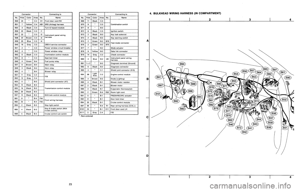
Connector
Connecting
to
No
.
Pole
Color
Area
No
.
Name
830
24
C-4
D1
Front
door
cord
RH
831
7
Yellow
C-4
A81
SRS
(Airbag)
harness
B32
3
Black
C-4
Turn
&
hazard
module
B36
22
Black
C-3
i1
B37
22
C-3
i2
Instrument
panel
wiring
B38
22
Brown
C-3
i3
harness
B39
20Blue
C-3
i4
B40
16
Gray
C-3
OBD-II
service
connector
B41
2
C-3
Power
window
circuit
breaker
842
4
C-3
Power
window
relay
B43
6
Black
C-3
Illumination
control
module
B44
8
C-3
Seat
belt
timer
B46
4
Green
B-4
Fuel
pump
relay
B47
6
Brown
B-4
Main
relay
B49
3
Black
B-4
Horn
relay
850
4
B-4
Blower
relay
851
11
Gray
C-4
FIB
B52
12
Gray
C-4
853
4
B-3
Shield
joint
connector
(AT)
B54
12
Black
B-3
B55
16
Black
B-3
Transmission
control
module
B56
20
Black
B-3
B57
12
Black
B-3
Shift-lock
control
module
861
B
B-4
F44
B62
20
B-4
F45
Front
wiring
harness
B64
2
Black
B-3
Stop
light
switch
B65
4
Black
B-3
Stop
&
brake
switch(Withcruise
control)
B68
5
i
Black
i
B-3
Cruise
control
sub
switch
Connector
Connecting
to
No
.
Pole
Color
Area
No
.
Name
B69
11
Black
C-3
B70
9
C-3
Combination
switch
B71
8
8-3
B72
6
Black
C-3
Ignition
switch
B73
2
Black
B-3
Key
lock
solenoid
B74
2
Black
B-3
Key
warning
switch
B75
2
Green
B-2
B76
B76
2
Green
&2
B75
Test
mode
connector
B77
7
B-2
Made
actuator
B78
9
Yellow
B-2
Data
link
connector
B79
14
Gray
C-2
Check
connector
B80
4
Blue
B-2
i20
Instrumentpanel
wiring
harness
B81
1
x
2
B-2
Diagnosis
terminal
(Ground)
B82
6
Black
B-2
Diagnosis
connector
B83
4
C-1
Shield
joint
connector
(E!G)
884
96
Light
blue
C-2
Engine
control
module
885
4
Brown
B-3
Diode
(Lighting)
B86
4
Black
B-1
Blower
motor
resistor
887
2
Black
B-1
Blower
motor
B88
3
Black
8-t
Evaporator
thermoswitch
890
2
Green
B-4
R50
Room
light
cord
B91
5B-1
FRESHIRECIRC
actuator
892
8
B-1
Door
lock
timer
B94
20
Black
B-1
Cruise
control
module
B97
56
B-4
R1Rear
wiring
harness
(S
.M
.J
.)
B101
24
B-1
D11
Front
doorcord
LH
13111
3
Gray
C-4
FIB
`
:
Non-colored
4
.
BULKHEAD
WIRING
HARNESS
(IN
COMPARTMENT)
A
B
C
1]
4
23
Page 209 of 2890
![SUBARU LEGACY 1996 Service Repair Manual 3-2
[rsPO]
AUTOMATIC
TRANSMISSION
AND
DIFFERENTIAL
8
.
Diagnostic
Chart
with
Select
Monitor
DISPLAY
LEDNo
.
Signal
name
Symbol
1
FWD
switch
FF
2
Kick-down
switch
KD
3
--
4
--
5
Brake
BR
6
ABS
SUBARU LEGACY 1996 Service Repair Manual 3-2
[rsPO]
AUTOMATIC
TRANSMISSION
AND
DIFFERENTIAL
8
.
Diagnostic
Chart
with
Select
Monitor
DISPLAY
LEDNo
.
Signal
name
Symbol
1
FWD
switch
FF
2
Kick-down
switch
KD
3
--
4
--
5
Brake
BR
6
ABS](/manual-img/17/57433/w960_57433-208.png)
3-2
[rsPO]
AUTOMATIC
TRANSMISSION
AND
DIFFERENTIAL
8
.
Diagnostic
Chart
with
Select
Monitor
DISPLAY
LEDNo
.
Signal
name
Symbol
1
FWD
switch
FF
2
Kick-down
switch
KD
3
--
4
--
5
Brake
BR
6
ABS
switch
AB
7
Cruise
control
set
CR
8
Power
switch
PW
9
-
-
10
t
-
--
I
-
FF
KDBR
ABCR
PW
DDDD
,o
DISPLAY
LEDNo
.
Signal
name
Symbol
1
N/P
range
switch
NP
2
R
range
switch
RR
3
D
range
switch
RD
43
range
switch
R3
5
2
range
switch
R2
6
1
range
switch
R1
7
Diagnosis
switch
SS
--
s
--
,o
_
1
-
NPRRRD
R3
R2
R1
SS
10
P
:
MODE
FAO
-
SWITCH
1
(SW1)
-
Reference
values
"
Lights
up
when
the
fuse
is
installed
in
FWD
switch
(No
.
1)
.
"
Lights
up
when
the
brake
pedal
is
depressed
(No
.
5)
"
Lights
up
when
the
ABS
signal
is
entered
(No
.
6)
.
"
Lights
up
when
the
cruise
control
is
set
(No
.
7)
.
NOTE
:
LED
Nos
.
2
and
8
do
not
come
on
.
Q
:
MODE
FA1
-
SWITCH
2
(SW2)
-
Reference
values
"
Lights
up
when
the
N
or
P
range
is
selected
(No
.
1)
.
"
Lights
up
when
the
R
range
is
selected
(No
.
2)
.
"
Lights
up
when
the
D
range
is
selected
(No
.
3)
.
"
Lights
up
when
the
3
range
is
selected
(No
.
4)
.
"
Lights
up
when
the
2
range
is
selected
(No
.
5)
.
"
Lights
up
when
the
1
range
is
selected
(No
.
6)
.
"
Lights
up
when
the
diagnosis
switch
is
connected
(No
.
7)
.
NOTE
:
If
each
LED
does
not
illuminate
in
the
above
conditions,
inhibitor
switch
malfunction
may
occur
.
Performdiagnos-
tics
on
inhibitor
switch
.
<
Ref
.
to
2-7
[T10AN0]
.*2
>
20
Page 220 of 2890
![SUBARU LEGACY 1996 Service Repair Manual
ON-BOARD
DIAGNOSTICS
11
SYSTEM
[T10A0]
2-7
10
.
Diagnostics
Chart
with
Trouble
Code
DTC
No
.
Abbreviation
(Subaru
select
monitor)Item
Page
P0500
VSP
Vehicle
speed
sensor
malfunction
1
P0505
I SUBARU LEGACY 1996 Service Repair Manual
ON-BOARD
DIAGNOSTICS
11
SYSTEM
[T10A0]
2-7
10
.
Diagnostics
Chart
with
Trouble
Code
DTC
No
.
Abbreviation
(Subaru
select
monitor)Item
Page
P0500
VSP
Vehicle
speed
sensor
malfunction
1
P0505
I](/manual-img/17/57433/w960_57433-219.png)
ON-BOARD
DIAGNOSTICS
11
SYSTEM
[T10A0]
2-7
10
.
Diagnostics
Chart
with
Trouble
Code
DTC
No
.
Abbreviation
(Subaru
select
monitor)Item
Page
P0500
VSP
Vehicle
speed
sensor
malfunction
'1
P0505
ISC
Idle
control
system
malfunction
`1
P0506
ISC
-
L
Idle
control
system
RPM
lower
than
expected
'1
P0507
ISC
-
H
Idle
control
system
RPM
higher
than
expected
'1
P0600
-
Serial
communication
link
malfunction
`1
P0601
RAM
Internal
control
module
memory
check
sum
error
'1
P0703
ATBRK
Brake
switch
input
malfunction
'1
P0705
ATRNG
Transmissionrange
sensor
circuit
malfunction
`1
P0710
ATF
Transmission
fluid
temperature
sensor
circuit
malfunction
'1
P0720
ATVSP
Output
speed
sensor
(vehicle
speed
sensor
1)
circuit
malfunction
'1
P0725
ATNE
Engine
speed
input
circuit
malfunction
'1
P0731
ATGR1
Gear
1
incorrect
ratio
P0732
ATGR2
Gear
2
incorrect
ratio
"
1
P0733
ATGR3
Gear
3
incorrect
ratio
P0734
ATGR4
Gear
4
incorrect
ratio
P0740
ATLU
-
F
Torque
converter
clutch
system
malfunction
1
P0743
ATLU
Torque
converter
clutch
system
electrical
*1
P0748
ATPL
Pressure
control
solenoid
electrical
'1
P0753
ATSFTi
Shift
solenoid
A
electrical
`1
P0758
ATSFT2
Shift
solenoid
B
electrical
'1
P0760
ATOVR
-
F
Shift
solenoid
C
malfunction
'1
P0763
ATOVR
Shift
solenoid
C
electrical
'1
P1100
ST-SW
Starter
switch
circuit
malfunction
'1
P1101
N/P
-
SW
Neutral
position
switch
circuit
malfunction
[MT
vehicles]
'1
P1101
N/P
-
SW
Neutral
position
switch
circuit
malfunction
[AT
vehicles]
1
P1102
BR
Pressure
sources
switching
solenoid
valve
circuit
malfunction
'1
P1103
TRQ
Engine
torque
control
signal
circuit
malfunction
`1
P1400
PCVSOL
Fueltank
pressure
control
solenoid
valve
circuit
malfunction
38
P1401
PCV
-
FFueltank
pressure
control
system
function
problem
44
P1402
FIVL
Fuel
level
sensor
circuit
malfunction
46
P1500
FAN
-
1
Radiator
fan
relay
1
circuit
malfunction
'1
P1502
FAN
-
F
Radiator
fan
function
problem
'1
P1700
ATTH
Throttle
position
sensor
circuit
malfunction
for
automatic
transmission
'1
P1701
ATCRS
Cruise
control
set
signal
circuit
malfunction
for
automatic
transmission
'1
P1702
ATDIAG
Automatic
transmission
diagnosis
inputsignal
circuit
malfunction
'1
P0461'2
EXERR22
Fuel
level
sensor
circuit
range/performance
problem
56
"1
:
<
Ref
.
to
2-7
[T11A0]
.*4
>
'2
:
Only
OBD-II
general
scan
tool
displays
DTC
.