Page 267 of 2890

6-3
IDso21
WIRING
DIAGRAM
6
.
Wiring
Diagram
6
.
Wiring
Diagram
2
.
GROUND
DISTRIBUTION
i26
Radio
Front
turn
signal
F3
and
sidemarker
z
light
RH
Cigarette
lighter
8~7
Mode
Flb
~
actuator
Subfan
motor
i
GR
f17
Main
fan
motor
11
Front
turn
signs
F~
and
sidemarker
light
LH
Turn
&
hazard
B32
module
Power
wind
relay
AT
shift
lock
control
module
B64
Seat
belt
timer[5
:ji
D66
Bleck>
2
(Brown)
i19
i1B
(B
I
e
C
K)
843
1
2
3456
B57
(g
I
ac
k)
123456
71319461111121
13
'D
2
box
iiio1vuemination
light
=
0
1
agnos
1
a
---B=
term
!
na
I
CD
E
T
B
Fan
switch
GB-7
L
+~
~
3
(9)Illumination
control
module
i
17
s
Mode
control
a
panel
-
om
FGS
L
O
oc
~
B71
3
e
Comb
i
nat
i
on
i18
C~'
sw
i
tch
Rear
defoggro0
switch
870
e
Combination
a
Cruise
control`-'switch
main
switch
b
:
i12
Combination
meter
emote
control
~
830
Combination
rearview
mirror
,
,switch
"J
switch
m
B39
B47
Mainrela
y
(B
r
own>
(B
r
own)
(~D(B
I
ack)
F1721
123
F1
f2T3-1
F1
r2
M
G31
M-
4
MS6
141516
(~~
(Brown)
(D
j
24
3
q
S6
1
23
F45T6
7
1
234
S678
PM
1
2
30
78
CD
(~D(Light
gray)
ill
Bleck>
F45
i4
(Blue)
123
456
12345678
234
6789
1
~~
7891011121314
12345678910111213141516
910111213141516
11
(21314151617181920
BUR04-03A
2
Page 268 of 2890

WIRING
DIAGRAM
[oso2i
6-3
6
.
Wiring
Diagram
GB-3
B3B
i3
i13
Comb
ination
'L~J
meter
B31
SRS
harness
BB
E
E
Frontwiper
[Uf
motor
4-6
GB-4
B9
FWD
sw
I
tch
CI
:~
816
Brakefluid
level
switch
Rear
Rear
finisherfinisher
light
LH
light
RH
049
8
D42
D4G
Lisence
plate
Iight
RH
D45
Lisence
plate
11ght
LH
043
Rearwipe
r
motor
048
Rear
defogge
r
R26
Rear
combination
LM
light
RH
R28
Rear
combination
LM
I(ght
LH
D46
Reargate
klatch
switch
R7
033R67
(B
I
ac
k)R6
i23
(BrowN
(B
I
ec
k)
B9
R25
(B
I
ec
k)
B16
(G
rey)
DB
(Gray)
D44045
21
2
12
1212
FI6
(B
I
ac
k)
B62D63R26
(B
I
ac
k)
039
12
BBB
(Black)
123
Fl7
(B
I
ac
k)
D49D42R2B
(B
I
ac
k)
(K)
(Y
e
11
ow)
(E)(9)
12
34
M1_2T3741
13141516
1
o23
N4
;5677
1
234
1
234
5
M67
8
R56
;7iR8
(B
I
8C
k)
(B
I
ac
K)
(Brown)
P
3141
56
789
1
F273
F1
4
6789
0151
7
89
1
2
34
161
2
314
0
1121314E
69
7181
1
11
1
12
1
314
51617
A
920
12
11112
314(51617
B4
02122
78
I
F1
34
161718
212223py
56
2~14
BUR04-03B
5
.
M
.
J
.
[Referto
foldout
page
.]
-
-
z~
B97
Rl
B92
Door
lock
module
B94
GB-8
Cruise
control
module
888
L=]
Evaporator
thermoswitch
R7
P
position
switch
R6
C
Shift
lock
solenoid
R46R67R58
Fuel
gauge
-e-C~umodule
&
fuel
pump
R25
LEE
Reardefogger
condenser
R23
-riPower
antenna
s1
-
~_5
GB-9
High-mounted
stop
light
D39
-12
m
R37
m4
D33
3
Page 525 of 2890
B2M0154
3. Throttle Body
A: REMOVAL AND INSTALLATION
1) Remove air intake duct.
G2M0280
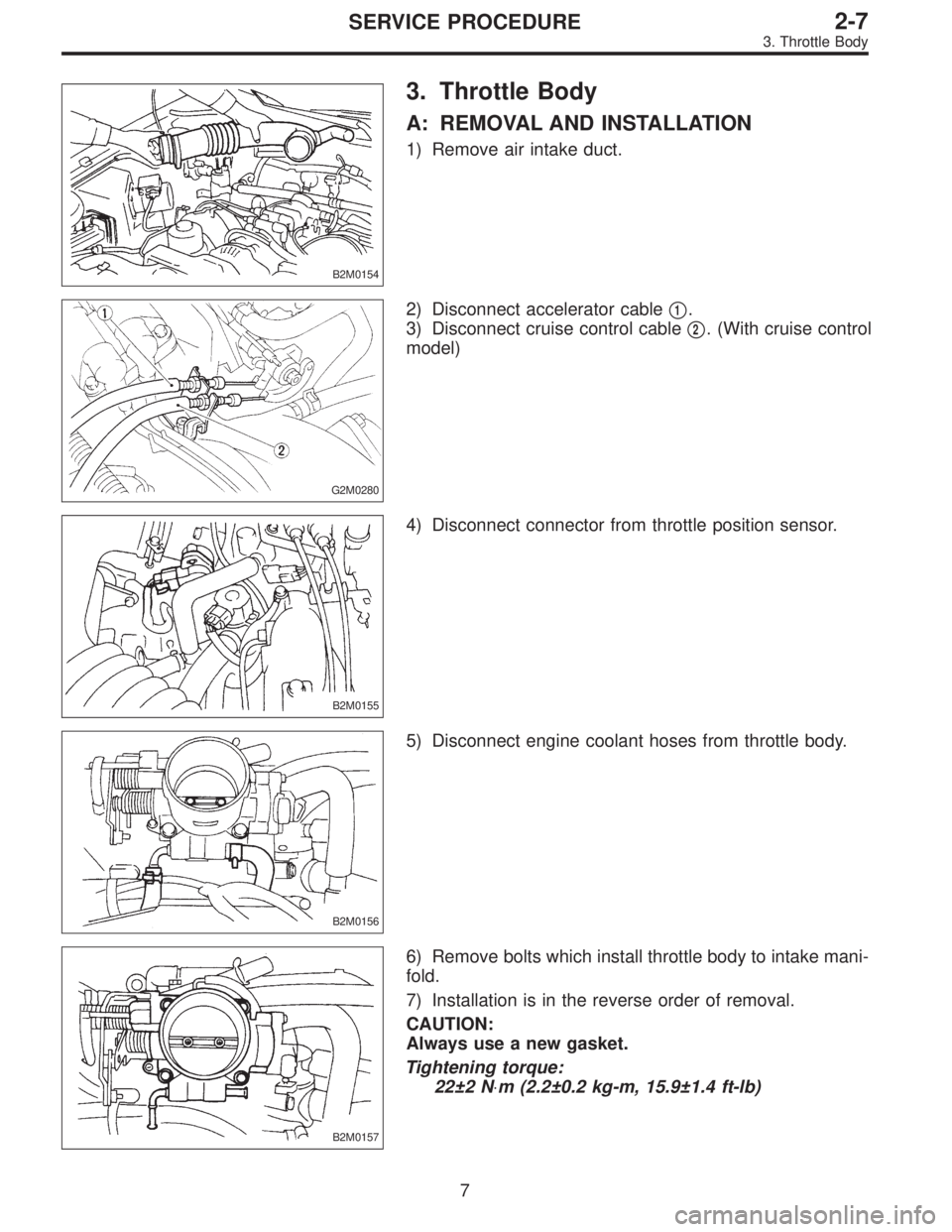
2) Disconnect accelerator cable�1.
3) Disconnect cruise control cable�
2. (With cruise control
model)
B2M0155
4) Disconnect connector from throttle position sensor.
B2M0156
5) Disconnect engine coolant hoses from throttle body.
B2M0157
6) Remove bolts which install throttle body to intake mani-
fold.
7) Installation is in the reverse order of removal.
CAUTION:
Always use a new gasket.
Tightening torque:
22±2 N⋅m (2.2±0.2 kg-m, 15.9±1.4 ft-lb)
7
2-7SERVICE PROCEDURE
3. Throttle Body
Page 526 of 2890
B2M0154
4. Intake Manifold
A: REMOVAL
1) Release fuel pressure.
2) Disconnect connector from mass air flow sensor.
3) Remove air intake duct, air cleaner upper cover and air
cleaner element.
G2M0280
4) Disconnect accelerator cable�1.
5) Disconnect cruise control cable�
2. (With cruise control
model)
B2M0334
6) Disconnect hoses from pressure sources switching
solenoid valve.
G2M0286
7) Remove power steering pump from bracket.
(1) Loosen lock bolt and slider bolt, and remove front
side V-belt.
B2M0340
(2) Remove pipe with bracket from intake manifold.
8
2-7SERVICE PROCEDURE
4. Intake Manifold
Page 535 of 2890
B2M0334
15) Install power steering pump on bracket.
(1) Install power steering pump on bracket, and tighten
bolts.
Tightening torque:
20.1±2.5 N⋅m (2.05±0.25 kg-m, 14.8±1.8 ft-lb)
B2M0340
(2) Install power steering pipe bracket on right side
intake manifold.
G2M0286
(3) Install front side V-belt, and adjust it.
B2M0017
(4) Install V-belt cover.
G2M0280
16) Connect accelerator cable�1.
17) Connect cruise control cable�
2. (With cruise control
model)
17
2-7SERVICE PROCEDURE
4. Intake Manifold
Page 627 of 2890
B2M0154
3. Throttle Body
A: REMOVAL AND INSTALLATION
1) Remove air intake duct.
G2M0280
2) Disconnect accelerator cable�1.
3) Disconnect cruise control cable�
2. (With cruise control
model)
B2M0155
4) Disconnect connector from throttle position sensor.
B2M0156
5) Disconnect engine coolant hoses from throttle body.
B2M0157
6) Remove bolts which install throttle body to intake mani-
fold.
7) Installation is in the reverse order of removal.
CAUTION:
Always use a new gasket.
Tightening torque:
22±2 N⋅m (2.2±0.2 kg-m, 15.9±1.4 ft-lb)
7
2-7SERVICE PROCEDURE
3. Throttle Body
Page 628 of 2890
B2M0154
4. Intake Manifold
A: REMOVAL
1) Release fuel pressure.
2) Disconnect connector from mass air flow sensor.
3) Remove air intake duct, air cleaner upper cover and air
cleaner element.
G2M0280
4) Disconnect accelerator cable�1.
5) Disconnect cruise control cable�
2. (With cruise control
model)
B2M0334
6) Disconnect hoses from pressure sources switching
solenoid valve.
G2M0286
7) Remove power steering pump from bracket.
(1) Loosen lock bolt and slider bolt, and remove front
side V-belt.
B2M0340
(2) Remove pipe with bracket from intake manifold.
8
2-7SERVICE PROCEDURE
4. Intake Manifold
Page 637 of 2890
B2M0334
15) Install power steering pump on bracket.
(1) Install power steering pump on bracket, and tighten
bolts.
Tightening torque:
20.1±2.5 N⋅m (2.05±0.25 kg-m, 14.8±1.8 ft-lb)
B2M0340
(2) Install power steering pipe bracket on right side
intake manifold.
G2M0286
(3) Install front side V-belt, and adjust it.
B2M0017
(4) Install V-belt cover.
G2M0280
16) Connect accelerator cable�1.
17) Connect cruise control cable�
2. (With cruise control
model)
17
2-7SERVICE PROCEDURE
4. Intake Manifold
![SUBARU LEGACY 1996 Service Repair Manual B2M0154
4. Intake Manifold
A: REMOVAL
1) Release fuel pressure. <Ref. to 2-8 [W1A0].>
2) Disconnect connector from mass air flow sensor.
3) Remove air intake duct, air cleaner upper cover and air
clea](/manual-img/17/57433/w960_57433-525.png "SUBARU LEGACY 1996 Service Repair Manual B2M0154
4. Intake Manifold
A: REMOVAL
1) Release fuel pressure. <Ref. to 2-8 [W1A0].>
2) Disconnect connector from mass air flow sensor.
3) Remove air intake duct, air cleaner upper cover and air
clea")
 Install power steering pump on bracket.
(1) Install power steering pump on bracket, and tighten
bolts.
Tightening torque:
20.1±2.5 N⋅m (2.05±0.25 kg-m, 14.8±1.8 ft-lb)
B2M0340
(2) Ins")

![SUBARU LEGACY 1996 Service Repair Manual B2M0154
4. Intake Manifold
A: REMOVAL
1) Release fuel pressure. <Ref. to 2-8 [W1A0].>
2) Disconnect connector from mass air flow sensor.
3) Remove air intake duct, air cleaner upper cover and air
clea](/manual-img/17/57433/w960_57433-627.png "SUBARU LEGACY 1996 Service Repair Manual B2M0154
4. Intake Manifold
A: REMOVAL
1) Release fuel pressure. <Ref. to 2-8 [W1A0].>
2) Disconnect connector from mass air flow sensor.
3) Remove air intake duct, air cleaner upper cover and air
clea")
 Install power steering pump on bracket.
(1) Install power steering pump on bracket, and tighten
bolts.
Tightening torque:
20.1±2.5 N⋅m (2.05±0.25 kg-m, 14.8±1.8 ft-lb)
B2M0340
(2) Ins")