Page 216 of 2890
![SUBARU LEGACY 1996 Service Repair Manual
ON-BOARD
DIAGNOSTICS
II
SYSTEM
[rsi2]
2-7
8
.
Diagnostics
for
Engine
Starting
Failure
WIRING
DIAGRAM
:
Fuel
pump
M
R58
S
.M
.J
.
R67R46
R1
897
E
B84
ECM
Fuel
pump
relay
0
846
SBF-2
No
.1 SUBARU LEGACY 1996 Service Repair Manual
ON-BOARD
DIAGNOSTICS
II
SYSTEM
[rsi2]
2-7
8
.
Diagnostics
for
Engine
Starting
Failure
WIRING
DIAGRAM
:
Fuel
pump
M
R58
S
.M
.J
.
R67R46
R1
897
E
B84
ECM
Fuel
pump
relay
0
846
SBF-2
No
.1](/manual-img/17/57433/w960_57433-215.png)
ON-BOARD
DIAGNOSTICS
II
SYSTEM
[rsi2]
2-7
8
.
Diagnostics
for
Engine
Starting
Failure
WIRING
DIAGRAM
:
Fuel
pump
M
R58
S
.M
.J
.
R67R46
R1
897
E
B84
ECM
Fuel
pump
relay
0
846
SBF-2
No
.16
~b---
862F45
884
9
10
1112
13141516
R58
R61B46
3132
333435363738
39
40
4142
43
44585960
6162
6364
6566
6768
6910
1
2
3
~1
]
M34
1
84
1
8
51
86
1
871
88
1
89
1
90
1
91
1
92
1
93
1
94
1
95
1
96
1
4
56~J
82M
1014
PUMpK
OPERATING
SOUND
OFFUEL
811
CHEC
R58
OBD0132A
Make
sure
that
fuel
pump
isin
operation
for
two
seconds
when
turning
ignition
switch
to
ON
.
CHECK
:
Does
fuel
pump
produce
operating
sound?
NOTE
:
Fuel
pump
operation
check
can
also
beexecuted
using
Subaru
Select
Monitor
(Function
mode
:
FD01)
.
For
the
procedure,
referto
"COMPULSORY
VALVE
OPER-
ATION
CHECK
MODE"
2-7
[T3F0]*4
.
,res
:
Check
fuel
injector
circuit
.
<
Ref
.
to
2-7
[T10Q0].*2
>
No
:
Go
to
step
812
.
1
812
CHECK
GROUND
CIRCUIT
OF
FUEL
PUMP
.
1)
Turn
ignition
switch
to
OFF
.
2)
Disconnect
connector
from
fuel
pump
.
3)
Measure
resistance
of
harness
connector
between
fuel
pump
and
chassis
ground
.
CHECK
:
Connector
&
terminal
(R58)
No
.
4
-
Chassis
ground
:
Is
the
resistance
less
than
5
S2?
5
Page 227 of 2890
2-7
[ryoaPO]
ON-BOARD
DIAGNOSTICS
II
SYSTEM
10
.
Diagnostics
Chart
with
Trouble
Code
OBD
(FBI)
P0181
H2M1350
BP
:
DTC
P0181
-
FUEL
TEMPERATURE
SENSOR
A
CIRCUIT
RANGE/PERFORMANCE
PROBLEM
(TN
KT
-
F)
-
DTC
DETECTINGCONDITION
:
Two
consecutive
trips
with
fault
10BP1
I
Check
DTC
P0180
on
display
.
CAUTION
:
After
repair
or
replacement
of
faultyparts,
conduct
CLEAR
MEMORY
and
INSPECTION
MODES
.
Ref
.
to
2-7
[T3D0]
and
[T3E0]
.*2
and
*4
>
WIRING
DIAGRAM
:
884
ECM
301
S
.M
.J
.
B91
R1
R15R57R58
Fuel
tank
Fuel
temperature
===@H
sensor
884B22
1
U34
U5U
78
U
1
2
34
1711811912012112212312
51
1152211523112152511526113'
68
55
91
1451461471481491501
47
1
01112
1/11/21/31141151761//1781/91601811821631
193142116
U
1121
E
1
23
4
1
b
1
65
3-7
10
1
[49
B2M1015
16
Page 230 of 2890
ON-BOARD
DIAGNOSTICS
II
SYSTEM
ITyoso2i
2-7
10
.
DiagnosticsChart
with
Trouble
Code
WIRING
DIAGRAM
:
Main
relay
0
0
847
884
77
ECM
V
897
R69
S
.M
.J
.
~°c~
Vent
control
solenoid
valve
R68
R57R15
Pressure
control
862F45
SBF-2
O~C)-
B
~E
822
O
E4
Purge
control
solenoid
valve
--{~J
solenoid
valve
B84R68
R69
R57847
822
E4
1
U
49
10
11
1
1314
1
16
1
234
171
1
811
9
12012112212
1113
63
1
36
44
444
M56
5678
49
1
63
55116
68
/Ul
1
3
9101112
9
19
~Lltu
~
4L_L51bIJ~l
13141516
B2M1017
10BQ1
I
CHECK
ANY
OTHER
DTC
(BESIDES
DTC
P0440)
ON
DISPLAY
.
Is
there
any
other
DTC
on
display?
Inspect
the
relevant
DTC
using
"10
.
Diagnostics
Chart
with
Trouble
Code,
2-7
[T10A0]"*7
.
No
:
Go
to
step
101302
.
FILLER
PIPE
.
FILLER
CAPAND
FUEL
1)
Turn
ignition
switch
to
OFF
.
2)
Open
the
fuelflap
.
CHECK
:
Is
the
fuel
filler
cap
tightened
securely?
Tighten
fuel
filler
cap
securely
.
o
:
Go
to
next
CHECK
.
19
Page 247 of 2890
2_7
[T10BT0]
ON-BOARD
DIAGNOSTICS
II
SYSTEM
10
.
Diagnostics
Chart
with
Trouble
Code
OBD
(FBI)
P0451
H2M
1377
BT
:
DTC
P0451
-
EVAPORATIVE
EMISSION
CONTROL
SYSTEM
PRESSURE
SENSOR
RANGE/PERFORMANCE
PROBLEM
(TNKP
-
F)
-
DTC
DETECTING
CONDITION
:
Two
consecutive
trips
with
fault
I
1OBT1
I
Check
pressure/vacuum
line
.
CAUTION
:
After
repair
or
replacement
of
faultyparts,
conduct
CLEAR
MEMORY
and
INSPECTION
MODES
.
c
Ref
.
to
2-7
[T3D0]
and
[T3E0]
.*2
and
*4
>
WIRING
DIAGRAM
:
S.M
.J
.
B84897
Ri
R47
Fuel
tankpressure
sensor
ECM
L,
884R47
u
u
u
su
1
71
18
1
1
91201211
2
212312412512612712
8
1
2
913011
78
5
go
8T7T
72
444
44
17374759
7
7
123
82M1019
36
Page 254 of 2890
2-7
[T1
oBVO1
ON-BOARD
DIAGNOSTICS
II
SYSTEM
10
.
Diagnostics
Chart
with
Trouble
Code
OBD
(FBI)
P1401
H21
M1410
BV
:
DTC
P1401
-
FUEL
TANK
PRESSURE
CONTROL
SYSTEM
FUNCTION
PROBLEM
(PCV
-
F)
-
DTC
DETECTING
CONDITION
:
Two
consecutive
trips
with
fault
10BV1
Check
fuel
tank
pressure
control
solenoid
valve
.
CAUTION
:
After
repair
or
replacement
of
faulty
parts,
conduct
CLEAR
MEMORY
and
INSPECTION
MODES
.
<
Ref
.
to
2-7
[T3D0]
and
[T3E0]
.*2
and
*4
>
WIRING
DIAGRAM
:
Main
relay
0
0
01F
B47861F45
SBF-2
B84
E
E)E)
ECM
ra
Ti
S
.M
.J
.
891
Rt
R15
R57R68
Fuel
tankpressure
control
solenoid
valve
847
R57R68
10
U
1112
U
131401
16
1
131
1
4041424344
1
2
960
6162
63
64
6
-769
69
70
34
1~,~y(3~
8
.04
687
8
99091929
949
96
6
14j5jti1/LtiJ
B2M1020
44
Page 265 of 2890
2-7
RyoBxo]
ON-BOARD
DIAGNOSTICS
II
SYSTEM
10
.
DiagnosticsChart
with
Trouble
Code
OBD
(
F
B
1)
EXERR22
B2M0947
BX
:
DTC
P0461
-
FUEL
LEVEL
SENSOR
CIRCUIT
RANGE/
PERFORMANCEPROBLEM
(EXERR22)
-
DTC
DETECTING
CONDITION
:
Two
consecutive
trips
with
fault
10BX1
Check
DTC
P1402
on
display
.
CAUTION
:
After
repair
or
replacement
of
faultyparts,
conduct
CLEAR
MEMORY
and
INSPECTION
MODES
.
<
Ref
.
to
2-7
[T3D0]
and
[T3E0]
.*2
and
*4
>
WIRING
DIAGRAM
:
a
:
(a)
b
:
i11
meter
Ignitionc
:
i14
B72
switch
No
.15
~
SBF-4
F
L
1
.25B
rill-fY~
f1
M
~^1-
~
.c
JL
S
.M
.J
.
O
O
897
R1
EW
8T2
1234
4U
i10i12
4
9
10
1
121
141
1
_
.
u
Fuel
pump
ASSY
R58
Fuellevel
r,r,
sensor
Fuel
sub
meter
unit
R59
Fuel.sub
R5787TR59
4W~!JJ
141~1b1
O
R5B
1
1
141~Ib1
82M1021
56
Page 1303 of 2890

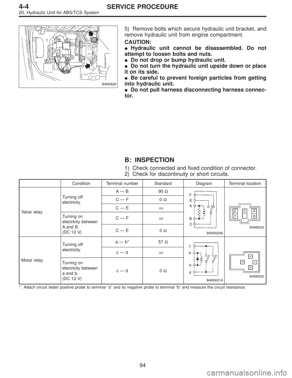
B4M0628
5) Remove bolts which secure hydraulic unit bracket, and
remove hydraulic unit from engine compartment.
CAUTION:
�Hydraulic unit cannot be disassembled. Do not
attempt to loosen bolts and nuts.
�Do not drop or bump hydraulic unit.
�Do not turn the hydraulic unit upside down or place
it on its side.
�Be careful to prevent foreign particles from getting
into hydraulic unit.
�Do not pull harness disconnecting harness connec-
tor.
B: INSPECTION
1) Check connected and fixed condition of connector.
2) Check for discontinuity or short circuits.
Condition Terminal number Standard Diagram Terminal location
Valve relayTurning off
electricity.A—B90Ω
B4M0629A
B4M0630
C—F0Ω
C—E
Turning on
electricity between
A and B.
(DC 12 V)C—F
C—E0Ω
Motor relayTurning off
electricity.a—b* 57Ω
B4M0631AB4M0632
c—d
Turning on
electricity between
a and b.
(DC 12 V)c—d0Ω
*: Attach circuit tester positive probe to terminal“a”and its negative probe to terminal“b”and measure the circuit resistance.
94
4-4SERVICE PROCEDURE
20. Hydraulic Unit for ABS/TCS System
Page 1716 of 2890

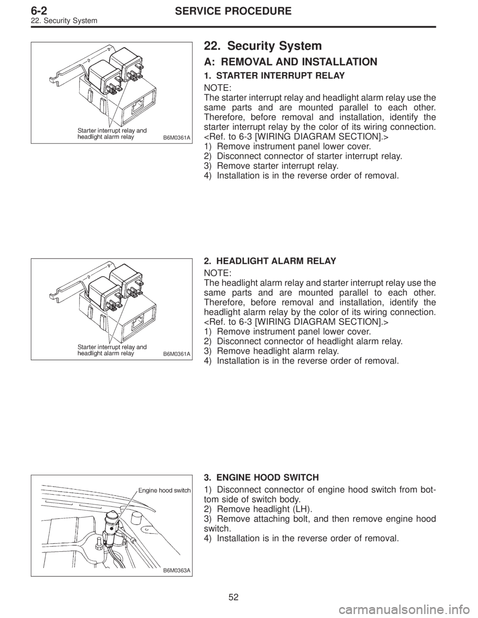
B6M0361A
22. Security System
A: REMOVAL AND INSTALLATION
1. STARTER INTERRUPT RELAY
NOTE:
The starter interrupt relay and headlight alarm relay use the
same parts and are mounted parallel to each other.
Therefore, before removal and installation, identify the
starter interrupt relay by the color of its wiring connection.
1) Remove instrument panel lower cover.
2) Disconnect connector of starter interrupt relay.
3) Remove starter interrupt relay.
4) Installation is in the reverse order of removal.
B6M0361A
2. HEADLIGHT ALARM RELAY
NOTE:
The headlight alarm relay and starter interrupt relay use the
same parts and are mounted parallel to each other.
Therefore, before removal and installation, identify the
headlight alarm relay by the color of its wiring connection.
1) Remove instrument panel lower cover.
2) Disconnect connector of headlight alarm relay.
3) Remove headlight alarm relay.
4) Installation is in the reverse order of removal.
B6M0363A
3. ENGINE HOOD SWITCH
1) Disconnect connector of engine hood switch from bot-
tom side of switch body.
2) Remove headlight (LH).
3) Remove attaching bolt, and then remove engine hood
switch.
4) Installation is in the reverse order of removal.
52
6-2SERVICE PROCEDURE
22. Security System