Page 1210 of 2890
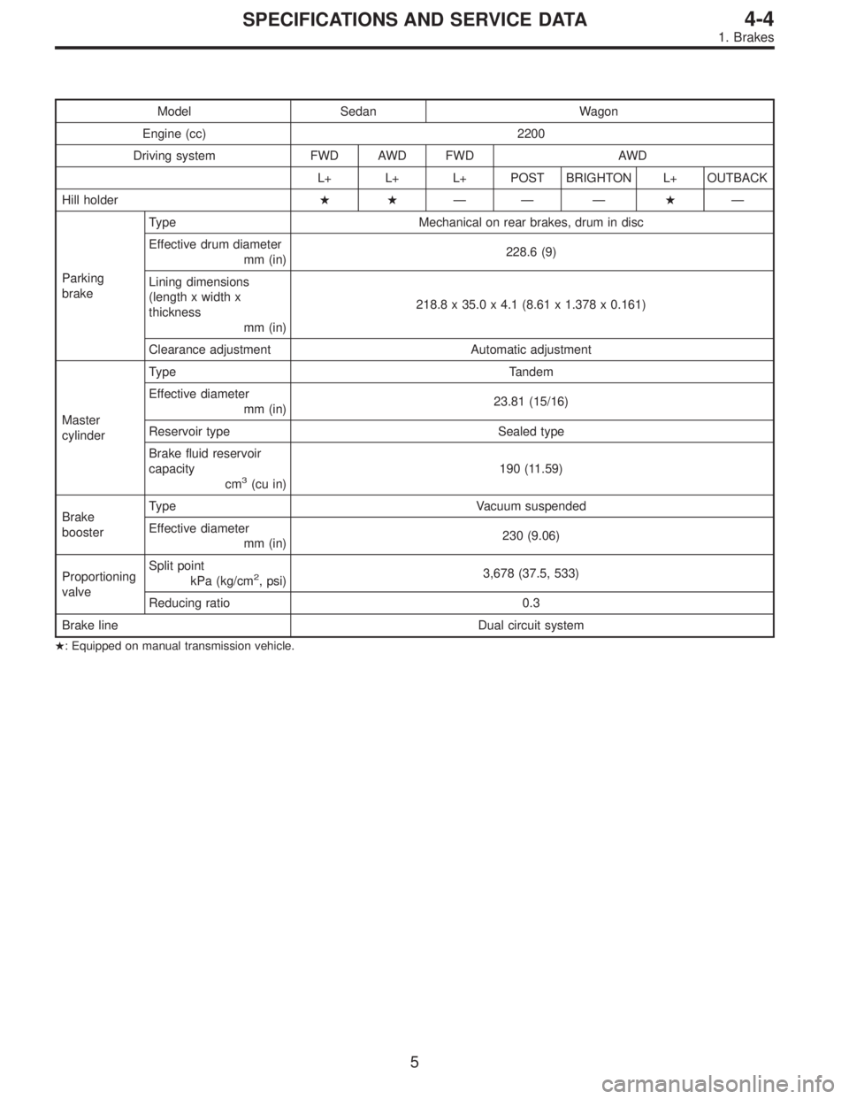
Model Sedan Wagon
Engine (cc) 2200
Driving system FWD AWD FWD AWD
L+ L+ L+ POST BRIGHTON L+ OUTBACK
Hill holder��—— —�—
Parking
brakeType Mechanical on rear brakes, drum in disc
Effective drum diameter
mm (in)228.6 (9)
Lining dimensions
(length x width x
thickness
mm (in)218.8 x 35.0 x 4.1 (8.61 x 1.378 x 0.161)
Clearance adjustment Automatic adjustment
Master
cylinderType Tandem
Effective diameter
mm (in)23.81 (15/16)
Reservoir type Sealed type
Brake fluid reservoir
capacity
cm
3(cu in)190 (11.59)
Brake
boosterType Vacuum suspended
Effective diameter
mm (in)230 (9.06)
Proportioning
valveSplit point
kPa (kg/cm
2, psi)3,678 (37.5, 533)
Reducing ratio 0.3
Brake line Dual circuit system
�: Equipped on manual transmission vehicle.
5
4-4SPECIFICATIONS AND SERVICE DATA
1. Brakes
Page 1282 of 2890
2. CHECKING THE HYDRAULIC UNIT OPERATION BY
PRESSURE GAUGE
1) Remove the FL and FR pipes from the hydraulic unit.
G4M0460
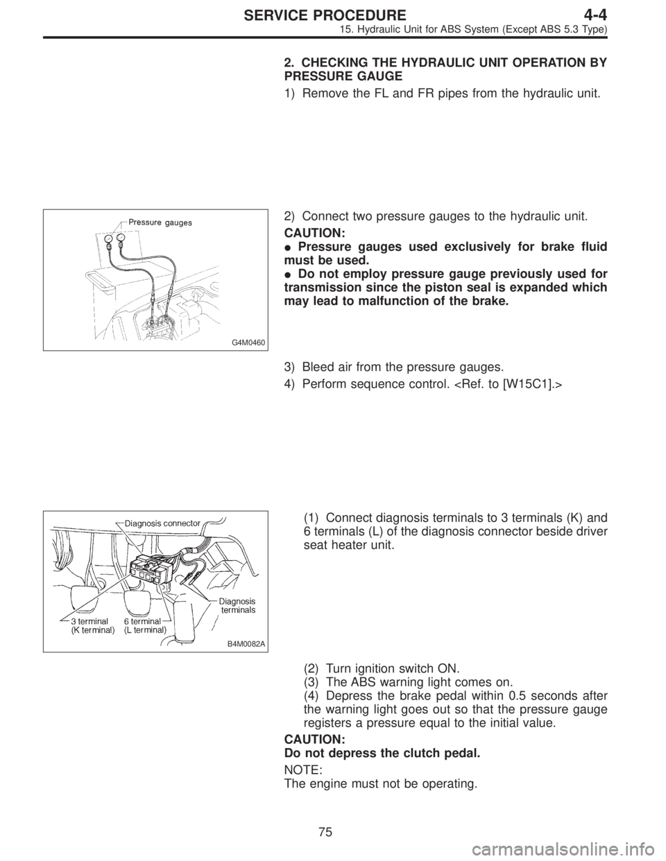
2) Connect two pressure gauges to the hydraulic unit.
CAUTION:
�Pressure gauges used exclusively for brake fluid
must be used.
�Do not employ pressure gauge previously used for
transmission since the piston seal is expanded which
may lead to malfunction of the brake.
3) Bleed air from the pressure gauges.
4) Perform sequence control.
B4M0082A
(1) Connect diagnosis terminals to 3 terminals (K) and
6 terminals (L) of the diagnosis connector beside driver
seat heater unit.
(2) Turn ignition switch ON.
(3) The ABS warning light comes on.
(4) Depress the brake pedal within 0.5 seconds after
the warning light goes out so that the pressure gauge
registers a pressure equal to the initial value.
CAUTION:
Do not depress the clutch pedal.
NOTE:
The engine must not be operating.
75
4-4SERVICE PROCEDURE
15. Hydraulic Unit for ABS System (Except ABS 5.3 Type)
Page 1304 of 2890
 Lift-up vehicle and remove wheels.
2) Disconnect the air bleeder screws from the FL and F")
C: CHECKING THE HYDRAULIC UNIT ABS
OPERATION
1. CHECKING THE HYDRAULIC UNIT ABS
OPERATION BY PRESSURE GAUGE
1) Lift-up vehicle and remove wheels.
2) Disconnect the air bleeder screws from the FL and FR
caliper bodies.
B4M0633A
3) Connect two pressure gauges to the FL and FR caliper
bodies.
CAUTION:
�Pressure gauges used exclusively for brake fluid
must be used.
�Do not employ pressure gauge previously used for
transmission since the piston seal is expanded which
may lead to malfunction of the brake.
NOTE:
Wrap sealing tape around the pressure gauge.
4) Bleed air from the pressure gauges.
5) Perform ABS sequence control.
6) When the hydraulic unit begins to work, and first the FL
side performs decompression, holding, and compression,
and then the FR side performs decompression, holding,
and compression.
7) Read values indicated on the pressure gauge and
check if the fluctuation of the values between decompres-
sion and compression meets the standard values. Also
check if any irregular brake pedal tightness is felt.
Initial value When decompressed When compressed
Front wheel 3,432 kPa (35 kg/cm
2, 498 psi)490 kPa (5 kg/cm2, 71 psi)
or less981 kPa (10 kg/cm2, 142 psi)
or more
Rear wheel 3,432 kPa (35 kg/cm
2, 498 psi)490 kPa (5 kg/cm2, 71 psi) or
less981 kPa (10 kg/cm2, 142 psi)
or more
8) Remove pressure gauges and air bleeder screws from
the RL and RR caliper bodies.
9) Connect the air bleeder screws hose to the FL and FR
caliper bodies.
10) Connect two pressure gauges to the RL and RR cali-
per bodies.
11) Bleed air from the pressure gauges and the FL and FR
caliper bodies.
12) Perform ABS sequence control.
[W20D0].>
13) When the hydraulic unit begins to work, at first the RR
side performs decompression, holding, and compression,
and then the RL side performs decompression, holding,
and compression.
14) Read values indicated on the pressure gauges and
check if they meet the standard value.
95
4-4SERVICE PROCEDURE
20. Hydraulic Unit for ABS/TCS System
Page 1310 of 2890
 Lift-up vehicle and remove wheels.
2) Disconnect the air bleeder screws from the FL and F")
E: CHECKING THE HYDRAULIC UNIT TCS
OPERATION
1. CHECKING THE HYDRAULIC UNIT TCS
OPERATION BY PRESSURE GAUGE
1) Lift-up vehicle and remove wheels.
2) Disconnect the air bleeder screws from the FL and FR
caliper bodies.
B4M0633A
3) Connect two pressure gauges to the FL and FR caliper
bodies.
CAUTION:
�Pressure gauges used exclusively for brake fluid
must be used.
�Do not employ pressure gauge previously used for
transmission since the piston seal is expanded which
may lead to malfunction of the brake.
NOTE:
Wrap sealing tape around the pressure gauge.
4) Bleed air from the pressure gauges.
5) Perform sequence control.
6) When the hydraulic unit begins to work, and first the FL
side performs compression, holding, and decompression,
and then the FR side performs compression, holding, and
decompression.
7) Read values indicated on the pressure gauge and
check if the fluctuation of the values between compression
and decompression meets the standard values. Also check
if any irregular brake pedal tightness is felt.
Initial value When compressed When decompressed
Front left wheel490 kPa (5 kg/cm
2, 71 psi)
or less1,471 kPa (15 kg/cm2, 213 psi)
or more490 kPa (5 kg/cm2, 71 psi)
or less
Front right wheel490 kPa (5 kg/cm
2, 71 psi)
or less1,471 kPa (15 kg/cm2, 213 psi)
or more490 kPa (5 kg/cm2, 71 psi)
or less
8) After checking, remove the pressure gauges from the
caliper bodies.
9) Connect the air bleeder screws to the FL and FR cali-
per bodies.
10) Bleed air from brake line.
101
4-4SERVICE PROCEDURE
20. Hydraulic Unit for ABS/TCS System
Page 1321 of 2890
 Check connected and fixed condition of connector.
2) Check valve relay and motor relay for discontinuity or
short circuits.
Condition Terminal number Standard Diagram Terminal locatio")
B: INSPECTION
1) Check connected and fixed condition of connector.
2) Check valve relay and motor relay for discontinuity or
short circuits.
Condition Terminal number Standard Diagram Terminal location
Valve relayTurning off
electricity.85—86 103±10Ω
G4M0456G4M0457
30—87a less than 0.5Ω
30—87 more than 1 MΩ
Turning on
electricity between
85 and 86.
(DC 12 V)30—87a more than 1 MΩ
30—87 less than 0.5Ω
Motor relayTurning off
electricity.85—86 80±8Ω
G4M0458G4M0459
30—87 more than 1 MΩ
Turning on
electricity between
85 and 86.
(DC 12 V)30—87 less than 0.5Ω
C: CHECKING THE HYDRAULIC UNIT ABS
OPERATION
1. CHECKING THE HYDRAULIC UNIT ABS
OPERATION BY PRESSURE GAUGE
1) Lift-up vehicle and remove wheels.
2) Disconnect the air bleeder screws from the FL and FR
caliper bodies.
B4M0633A
3) Connect two pressure gauges to the FL and FR caliper
bodies.
CAUTION:
�Pressure gauges used exclusively for brake fluid
must be used.
�Do not employ pressure gauge previously used for
transmission since the piston seal is expanded which
may lead to malfunction of the brake.
NOTE:
Wrap sealing tape around the pressure gauge.
111
4-4SERVICE PROCEDURE
22. Hydraulic Unit for ABS System (ABS 5.3 Type)
Page 1892 of 2890
Item Page
P0500 VSP Vehicle speed sensor malfunction 266
P0505 ISC Idle control system malfunction 269
P0506 ISC
—L Idle control system RPM lower than expe")
DTC
No.Abbreviation
(Subaru select monitor)Item Page
P0500 VSP Vehicle speed sensor malfunction 266
P0505 ISC Idle control system malfunction 269
P0506 ISC
—L Idle control system RPM lower than expected 276
P0507 ISC
—H Idle control system RPM higher than expected 277
P0600—Serial communication link malfunction 278
P0601 RAM Internal control module memory check sum error 281
P0703 ATBRK Brake switch input malfunction 283
P0705 ATRNG Transmission range sensor circuit malfunction 286
P0710 ATF Transmission fluid temperature sensor circuit malfunction 293
P0720 ATVSP Output speed sensor (vehicle speed sensor 1) circuit malfunction 294
P0725 ATNE Engine speed input circuit malfunction 295
P0731 ATGR1 Gear 1 incorrect ratio
296 P0732 ATGR2 Gear 2 incorrect ratio
P0733 ATGR3 Gear 3 incorrect ratio
P0734 ATGR4 Gear 4 incorrect ratio
P0740 ATLU
—F Torque converter clutch system malfunction 300
P0743 ATLU Torque converter clutch system electrical 304
P0748 ATPL Pressure control solenoid electrical 305
P0753 ATSFT1 Shift solenoid A electrical 306
P0758 ATSFT2 Shift solenoid B electrical 307
P0760 ATOVR
—F Shift solenoid C malfunction 308
P0763 ATOVR Shift solenoid C electrical 312
P1100 ST
—SW Starter switch circuit malfunction 313
P1101 N/P
—SW Neutral position switch circuit malfunction [MT vehicles] 315
P1101 N/P
—SW Neutral position switch circuit malfunction [AT vehicles] 318
P1102 BR Pressure sources switching solenoid valve circuit malfunction 322
P1103 TRQ Engine torque control signal circuit malfunction 328
P1400 PCVSOL Fuel tank pressure control solenoid valve circuit malfunction 331
P1401 PCV
—F Fuel tank pressure control system function problem 337
P1402 FLVL Fuel level sensor circuit malfunction 339
P1500 FAN
—1 Radiator fan relay 1 circuit malfunction 351
P1502 FAN
—F Radiator fan function problem 358
P1700 ATTH Throttle position sensor circuit malfunction for automatic transmission 361
P1701 ATCRS Cruise control set signal circuit malfunction for automatic transmission 362
P1702 ATDIAG Automatic transmission diagnosis input signal circuit malfunction 365
P0461*1 EXERR22 Fuel level sensor circuit range/performance problem 368
*1: Only OBD-II general scan tool displays DTC.
124
2-7ON-BOARD DIAGNOSTICS II SYSTEM
10. Diagnostics Chart with Trouble Code
Page 2061 of 2890
OBD0380
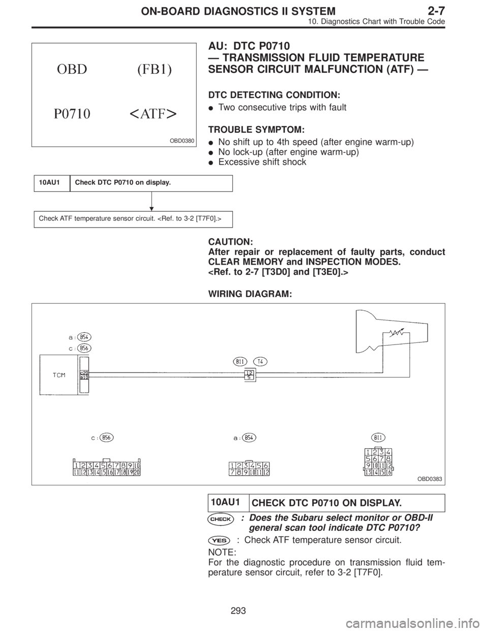
AU: DTC P0710
—TRANSMISSION FLUID TEMPERATURE
SENSOR CIRCUIT MALFUNCTION (ATF)—
DTC DETECTING CONDITION:
�Two consecutive trips with fault
TROUBLE SYMPTOM:
�No shift up to 4th speed (after engine warm-up)
�No lock-up (after engine warm-up)
�Excessive shift shock
10AU1Check DTC P0710 on display.
Check ATF temperature sensor circuit.
CAUTION:
After repair or replacement of faulty parts, conduct
CLEAR MEMORY and INSPECTION MODES.
WIRING DIAGRAM:
OBD0383
10AU1
CHECK DTC P0710 ON DISPLAY.
: Does the Subaru select monitor or OBD-II
general scan tool indicate DTC P0710?
: Check ATF temperature sensor circuit.
NOTE:
For the diagnostic procedure on transmission fluid tem-
perature sensor circuit, refer to 3-2 [T7F0].
�
293
2-7ON-BOARD DIAGNOSTICS II SYSTEM
10. Diagnostics Chart with Trouble Code
Page 2849 of 2890

Connector Connecting to
No. Pole Color Area No. Name
B1 2 * B-2 Pressure source switching solenoid
B2 3 Black B-2 Pressure sensor
B3 5 Gray B-2 Mass air flow sensor
B4 2 Gray B-2 AT dropping resistor
B5 2 Gray B-2 Resistor (Daytime running light)
B62 Gray B-2 ABS front sensor RH
2 Brown B-2 ABS front sensor RH (Outback with step roof)
B7 4 * B-2 Cruise control pump
B8 6 * A-2 Front wiper motor
B9 2 Black A-2 FWD switch (AT)
B10 2 Brown B-2 A/C pressure switch
B11 16 Gray B-3 T4
Transmission (AT)
B12 12 Gray B-2 T3
B13 6 Gray B-3 Ignitor
B14 1 Black B-3 Starter (Magnet)
B152 Gray B-3 ABS front sensor LH
2 Brown B-3 ABS front sensor LH (Outback with step roof)
B16 2 Gray B-3 Brake fluid level switch
B17 2 Black B-2 Vehicle speed sensor
B18 3 Dark gray B-2 Front oxygen sensor
B194 * B-2 T5 Rear oxygen sensor cord (Other models)
4 * B-2 Rear oxygen sensor (California model)
B20 6 Light gray B-2 E1
Engine wiring harness B21 12 Light gray B-2 E2
B22 16 Light gray B-2 E3
B24 2 Gray B-2 T1 Back-up light switch (MT)
B25 2 Brown B-2 T2 Neutral position switch (MT)
*: Non-colored
11 9
6-3WIRING DIAGRAM
8. Electrical Wiring Harness and Ground Point