Page 37 of 2890
2-7
[T3C14]
ON-BOARD
DIAGNOSTICS
II
SYSTEM
3
.
Diagnosis
System
THV
(F07
)
0%
0
.
21V
82M0482
TIM
(
F08
)
2
.
82
mS
B2M0483
ISC
(F09)
35.7
B2M0484
LOAD
(F10)
10
.0
B2M0485
02
(1`11)
0
.
60
V
B2M0486
14
.
FUNCTION
MODE
:
F07
-
THROTTLE
POSITION
SIGNAL
(THV)
-
*
Throttleposition
is
indicated
in
percentage
(%)and
voltage
(V)
at
the
same
time
.
NOTE
:
Be
sure
that
the
displayed
value
changes
smoothly
when
changing
throttle
valve
from
fully
closed
to
fully
opened
.
15
.
FUNCTION
MODE
:
F08
-
INJECTOR
PULSE
WIDTH
(TIM)
-
16
.
FUNCTION
MODE
:
F09
-
IDLE
AIR
CONTROL
SIGNAL
(ISC)
-
17
.
FUNCTION
MODE
:
F10
-
LOADDATA
(LOAD)
-
18
.
FUNCTION
MODE
:
F11
-
FRONT
OXYGEN
SENSOR
OUTPUT
SIGNAL
(02)
-
22
Page 259 of 2890
![SUBARU LEGACY 1996 Service Repair Manual
ON-BOARD
DIAGNOSTICS
II
SYSTEM
[r1oBwa]
2-7
10
.
Diagnostics
Chart
with
Trouble
Code
FLEVEL
(F45)
2
.50V
H2M1327
3
2
1
5
4
D
S2
B2M0935
I
CHECK
:
Does
the
value
change
less
than
0
.12
Vby
s](/manual-img/17/57433/w960_57433-258.png "SUBARU LEGACY 1996 Service Repair Manual
ON-BOARD
DIAGNOSTICS
II
SYSTEM
[r1oBwa]
2-7
10
.
Diagnostics
Chart
with
Trouble
Code
FLEVEL
(F45)
2
.50V
H2M1327
3
2
1
5
4
D
S2
B2M0935
I
CHECK
:
Does
the
value
change
less
than
0
.12
Vby
s")
ON-BOARD
DIAGNOSTICS
II
SYSTEM
[r1oBwa]
2-7
10
.
Diagnostics
Chart
with
Trouble
Code
FLEVEL
(F45)
2
.50V
H2M1327
3
2
1
5
4
D
S2
B2M0935
I
CHECK
:
Does
the
value
change
less
than
0
.12
Vby
shaking
harness
and
connector
of
ECM
while
monitoring
the
value
with
Subaru
Select
Monitor?
9
Subaru
Select
Monitor
Designate
mode
using
function
key
.
Function
mode
:
F45
9
F45
:
Fuel
level
sensor
output
signal
is
indicated
.
,rES
:
Repair
poor
contact
in
ECM
connector
.
No
:
Even
if
MIL
lights
up,
the
circuit
has
returned
to
a
normal
condition
at
this
time
.
A
temporary
poor
contact
of
the
connector
may
be
the
cause
.
NOTE
:
In
this
case,
repair
the
following
:
"
Poor
contact
in
fuel
pump
connector
"
Poor
contact
in
combination
meter
connector
"
Poor
contact
in
ECM
connector
"
Poor
contact
in
coupling
connector
(i3,
1322,
B97and
R57)
10BW4
CHECK
FUEL
LEVEL
SENSOR
.
1)
Turn
ignition
switch
to
OFF
.
2)
Remove
fuel
pump
access
hole
lid
located
on
the
right
rear
of
luggage
compartment
floor
.
3)
Disconnect
connector
from
fuel
pump
.
4)
Measure
resistance
between
connector
terminals
of
fuel
pump
.
CHECK
:
Terminals
No
.
3
-
No
.
5
:
Is
the
resistance
less
than
100
S2?
vES
:
Go
to
step
10BW5
.
No
:
Replace
fuel
sending
unit
.
49
Page 887 of 2890
 Tighten four bolts to secure the roller bearing.
Tightening torque:
39±3 N⋅m (4.0±0.3 kg-m, 28.9±2.2 ft-lb)
G3M0883
(3) Install the oil pump housing assembly to the torque
converter c")
G3M0383
(2) Tighten four bolts to secure the roller bearing.
Tightening torque:
39±3 N⋅m (4.0±0.3 kg-m, 28.9±2.2 ft-lb)
G3M0883
(3) Install the oil pump housing assembly to the torque
converter clutch case, and secure evenly by tightening
four bolts.
Tightening torque:
41±3 N⋅m (4.2±0.3 kg-m, 30.4±2.2 ft-lb)
CAUTION:
�Thoroughly remove the liquid gasket from the case
mating surface beforehand.
�Use an old gasket or an aluminum washer so as not
to damage the mating surface of the housing.
G3M0384
(4) Rotate the drive pinion several times with ST1 and
ST2.
ST1 498937100 HOLDER
ST2 499787100 WRENCH
G3M0884
(5) Tighten the LH retainer until contact is felt while
rotating the shaft. Then loosen the RH retainer. Keep
tightening the LH retainer and loosening the RH
retainer until the pinion shaft can no longer be turned.
This is the“zero”state.
G3M0885
(6) After the“zero”state is established, back off the LH
retainer 3 notches and secure it with the lock plate.
Then back off the RH retainer and retighten until it
stops. Repeat this procedure several times. Tighten the
RH retainer 1-3/4 notches further. This sets the preload.
Finally, secure the retainer with its lock plate.
NOTE:
Turning the retainer by one tooth changes the backlash
about 0.05 mm (0.0020 in).
61
3-2SERVICE PROCEDURE
4. Overall Transmission
Page 1013 of 2890

Left side Right side
Toe-in is
increased.
B4M0191A
Turn adjusting
wheel
counterclockwise
and adjusting bolt
clockwise.
B4M0351A
Turn adjusting
wheel clockwise
and adjusting bolt
counterclockwise.
Toe-in is
decreased.
B4M0351A
Turn adjusting
wheel clockwise
and adjusting bolt
counterclockwise.
B4M0191A
Turn adjusting
wheel
counterclockwise
and adjusting bolt
clockwise.
G4M0485
NOTE:
�When left and right wheels are adjusted for toe-in at the
same time, moving one scale graduation changes toe-in by
approximately 4 mm (0.16 in).
�Turn adjusting wheel and adjusting bolt equally in oppo-
site directions so that same scale graduations are posi-
tioned directly above center of the adjusting bolt.
3) Tighten self-locking nut.
Tightening torque:
137±20 N⋅m (14±2 kg-m, 101±14 ft-lb)
M4A0059
5. REAR WHEEL TOE-IN (AWD MODEL)
�Inspection
1) Using a toe-in gauge, measure rear wheel toe-in.
Toe-in: 0±3 mm (0±0.12 in)
2) Mark rear sides of left and right tires at height corre-
sponding to center of spindles and measure distance“B”
between marks.
3) Move vehicle forward so that marks line up with front
sides at height corresponding to center of spindles.
4) Measure distance“A”between left and right marks.
Toe-in can then be obtained by the following equation:
B�A = Toe-in
12
4-1SERVICE PROCEDURE
1. On-car Services
Page 1014 of 2890
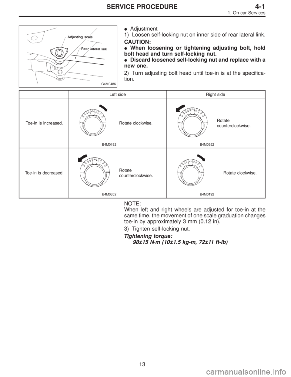
G4M0486
�Adjustment
1) Loosen self-locking nut on inner side of rear lateral link.
CAUTION:
�When loosening or tightening adjusting bolt, hold
bolt head and turn self-locking nut.
�Discard loosened self-locking nut and replace with a
new one.
2) Turn adjusting bolt head until toe-in is at the specifica-
tion.
Left side Right side
Toe-in is increased.
B4M0192
Rotate clockwise.
B4M0352
Rotate
counterclockwise.
Toe-in is decreased.
B4M0352
Rotate
counterclockwise.
B4M0192
Rotate clockwise.
NOTE:
When left and right wheels are adjusted for toe-in at the
same time, the movement of one scale graduation changes
toe-in by approximately 3 mm (0.12 in).
3) Tighten self-locking nut.
Tightening torque:
98±15 N⋅m (10±1.5 kg-m, 72±11 ft-lb)
13
4-1SERVICE PROCEDURE
1. On-car Services
Page 1188 of 2890
 Fee")
10. Power Steering Fluid
A: RECOMMENDED AIR BLEEDING AND
POWER STEERING FLUID
Recommended power steering fluid Manufacturer
ATF DEXRON II or ATF DEXRON IIEB.P.
CALTEX
CASTROL
MOBIL
SHELL
TEXACO
1) Feed the specified fluid with its level being about 5 cm
(2.0 in) lower than the mouth of tank.
2) Continue to turn steering wheel slowly from lock to lock
until bubbles stop appearing in the tank while keeping the
fluid at that level.
3) In case air is absorbed to deliver bubbles into piping
because the fluid level is lower, leave it about half an hour
and then do the step 2) all over again.
4) Start, and idle the engine.
5) Continue to turn steering wheel slowly from lock to lock
again until bubbles stop appearing in the tank while keep-
ing the fluid at that level.
It is normal that bubbles stop appearing after three times
turning of steering wheel.
6) In case bubbles do not stop appearing in the tank, leave
it about half an hour and then do the step 5) all over again.
7) Stop the engine, and take out safety stands after jack-
ing up vehicle again.
Then lower the vehicle, and idle the engine.
8) Continue to turn steering wheel from lock to lock until
bubbles stop appearing and change of the fluid level is
within 3 mm (0.12 in).
9) In case the following happens, leave it about half an
hour and then do step 8) again.
(1) The fluid level changes over 3 mm (0.12 in).
(2) Bubbles remain on the upper surface of the fluid.
(3) Grinding noise is generated from oil pump.
81
4-3SERVICE PROCEDURE
10. Power Steering Fluid
Page 1258 of 2890

G4M0744
2. AIR TIGHTNESS CHECK
Start engine, and run it for 1 to 2 minutes, then turn it off.
Depress brake pedal several times applying the same
pedal force as that used in ordinary braking operations.
The pedal stroke should be greatest on the 1st depression,
and it should become smaller with each successive
depression. If no change occurs in the pedal height while
in a depressed state, brake booster is faulty.
NOTE:
�In the event of defective operation, inspect the condition
of the check valve and vacuum hose.
�Replace them if faulty and conduct the test again.
�If no improvement is observed, check precisely with
gauges.
G4M0914
3. OPERATION CHECK
1) With engine off, depress brake pedal several times
applying the same pedal force and make sure that the
pedal height does not vary with each depression of the
pedal.
2) With brake pedal depressed, start engine.
3) As engine starts, brake pedal should move slightly
toward the floor. If no change occurs in the pedal height,
brake booster is faulty.
NOTE:
If faulty, check precisely with gauges.
4. LOADED AIR TIGHTNESS CHECK
Depress brake pedal while engine is running, and turn off
engine while the pedal is still depressed. Keep the pedal
depressed for 30 seconds; if no change occurs in the pedal
height, brake booster is functioning normally; if the pedal
height increases, it is faulty.
NOTE:
If faulty, check precisely with gauges.
52
4-4SERVICE PROCEDURE
6. Brake Booster
Page 1809 of 2890
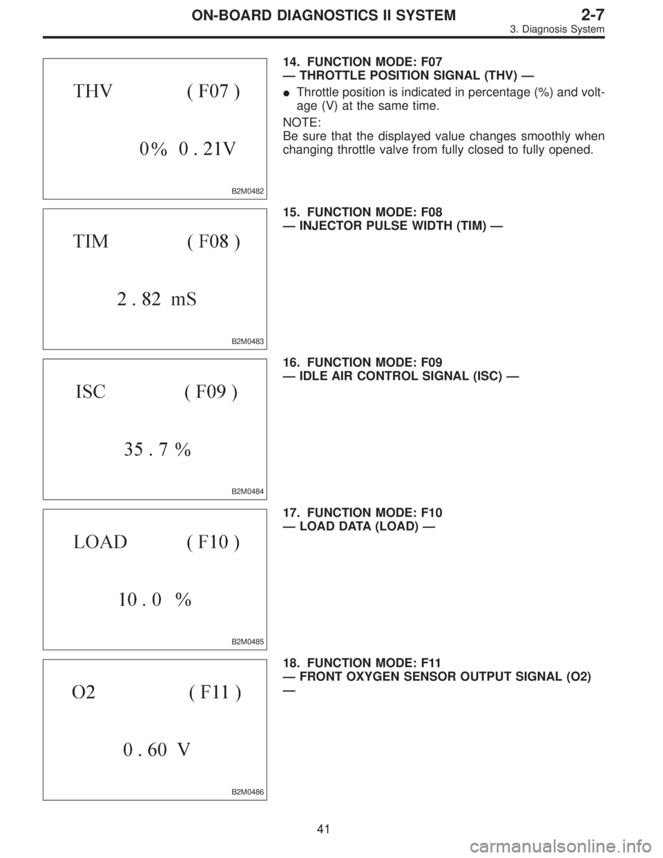
B2M0482
14. FUNCTION MODE: F07
—THROTTLE POSITION SIGNAL (THV)—
�Throttle position is indicated in percentage (%) and volt-
age (V) at the same time.
NOTE:
Be sure that the displayed value changes smoothly when
changing throttle valve from fully closed to fully opened.
B2M0483
15. FUNCTION MODE: F08
—INJECTOR PULSE WIDTH (TIM)—
B2M0484
16. FUNCTION MODE: F09
—IDLE AIR CONTROL SIGNAL (ISC)—
B2M0485
17. FUNCTION MODE: F10
—LOAD DATA (LOAD)—
B2M0486
18. FUNCTION MODE: F11
—FRONT OXYGEN SENSOR OUTPUT SIGNAL (O2)
—
41
2-7ON-BOARD DIAGNOSTICS II SYSTEM
3. Diagnosis System
![SUBARU LEGACY 1996 Service Repair Manual 2-7
[T3C14]
ON-BOARD
DIAGNOSTICS
II
SYSTEM
3
.
Diagnosis
System
THV
(F07
)
0%
0
.
21V
82M0482
TIM
(
F08
)
2
.
82
mS
B2M0483
ISC
(F09)
35.7
B2M0484
LOAD
(F10)
10
.0
B2M0485
02
(1`11)
0
.](/manual-img/17/57433/w960_57433-36.png "SUBARU LEGACY 1996 Service Repair Manual 2-7
[T3C14]
ON-BOARD
DIAGNOSTICS
II
SYSTEM
3
.
Diagnosis
System
THV
(F07
)
0%
0
.
21V
82M0482
TIM
(
F08
)
2
.
82
mS
B2M0483
ISC
(F09)
35.7
B2M0484
LOAD
(F10)
10
.0
B2M0485
02
(1`11)
0
.")