Page 3 of 2890
1-3
[0301]
GENERAL
INFORMATION
3
.
Vehicle
Identification
Numbers
(V
.I
.N)
3
.
Vehicle
Identification
Numbers
(V
.I
.N)
1
.
APPLICABLE
V
.I
.N
.
IN
THIS
MANUAL
Station
2200
cc
AWD
~
4AT
T
4
TS
3
1
B
I
KT
I
9
I
5X
I
T
I
8
I
T
2
00
1
and
after
Wagon
engine
POST
2
.
THE
MEANINGOF
V
.I
.N
.
Marker
identifier
l
Stop-
mark
4
S
3
Sequential
number
302001
and
after
:
Station
Wagon
Plant
of
manufacture
and
transmission
type
Plant
of
manufacture
Transmissiontype
SIA
POST
8
(Full-time
AWD
4AT)
Model
year
T
1996
Check
digit
Weight
class
and
restraint
type
Passenger
car
5
:
Withoutpassive
restraint,
with
Dual
SRS
airbag
Model
9
:
POST
Engine
type
4
:
2
.2
liter
engine
Body
type
K
:
Station
Wagon
Line
B
:
SUBARU
B
line
Plant
of
manufacture
Plant
of
manufacture
Type
of
vehicle
SIA
I
4S3
~
Passenger
car
I
Vehicle
attributes
Check
digit
Vehicle
identification
BK
495
X
T
83
0200
1
[
TT
I
T
T
ITT
Z
Stop
mark
2
Page 18 of 2890
![SUBARU LEGACY 1996 Service Repair Manual
ON-BOARD
DIAGNOSTICS
II
SYSTEM
[Tiq2]
2-
1
.
General
1~
Engine
control
module
(ECM)
~
Radiator
fan
~2
Ignition
coil~s
Radiator
fan
relay
~3
Ignitqr
~s
Pressure
sources
switching
solenoid
valve
~ SUBARU LEGACY 1996 Service Repair Manual
ON-BOARD
DIAGNOSTICS
II
SYSTEM
[Tiq2]
2-
1
.
General
1~
Engine
control
module
(ECM)
~
Radiator
fan
~2
Ignition
coil~s
Radiator
fan
relay
~3
Ignitqr
~s
Pressure
sources
switching
solenoid
valve
~](/manual-img/17/57433/w960_57433-17.png)
ON-BOARD
DIAGNOSTICS
II
SYSTEM
[Tiq2]
2-
1
.
General
1~
Engine
control
module
(ECM)
~
Radiator
fan
~2
Ignition
coil~s
Radiator
fan
relay
~3
Ignitqr
~s
Pressure
sources
switching
solenoid
valve
~4
Crankshaft
position
sensor
~
Knock
sensor
~5
Camshaft
position
sensor
~
Back-pressure
transducer
Throttle
position
sensor
~s
Front
oxygen
sensor
~7
duel
injectors
~o
Rear
oxygen
sensor
(Except
California
model)
~8
Pressure
regulator
~
Pressure
sensor
Engine
coolant
temperature
sensor
~z
A/C
compressor
~o
Mass
air
flow
sensor
~
Inhibitor
switch
Idle
air
control
solenoid
valve
~
CHECK
ENGINE
malfunction
indicator
lamp
(MIL)
~z
Purge
control
solenoid
valve
~
Tachometer
0
Fuel
pump
~s
A/C
relay
0
PCV
valve
~
A/C
control
module
~s
Air
cleaner
~eIgnition
switch
Canister
~
Transmission
control
module
(TCM)
~
Main
relay
~o
Vehicle
speed
sensor
2
~a
Fuel
pump
relay
~
Data
link
connector
(For
Subaru
select
monitor)
~s
Fuel
filter
@
Data
link
connector
(For
Subaru
select
monitor
and
~o
Front
catalytic
converter
OBD-II
general
scan
tool)
Rear
catalytic
converter
@
Two
way
valve
~2
MGR
valve
~a
Rear
oxygen
sensor
(California
model
only)
EGR
control
solenoid
valve
~
Filter
3
Page 66 of 2890

ON-BOARD
DIAGNOSTICS
II
SYSTEM
[Tsn2i
2-7
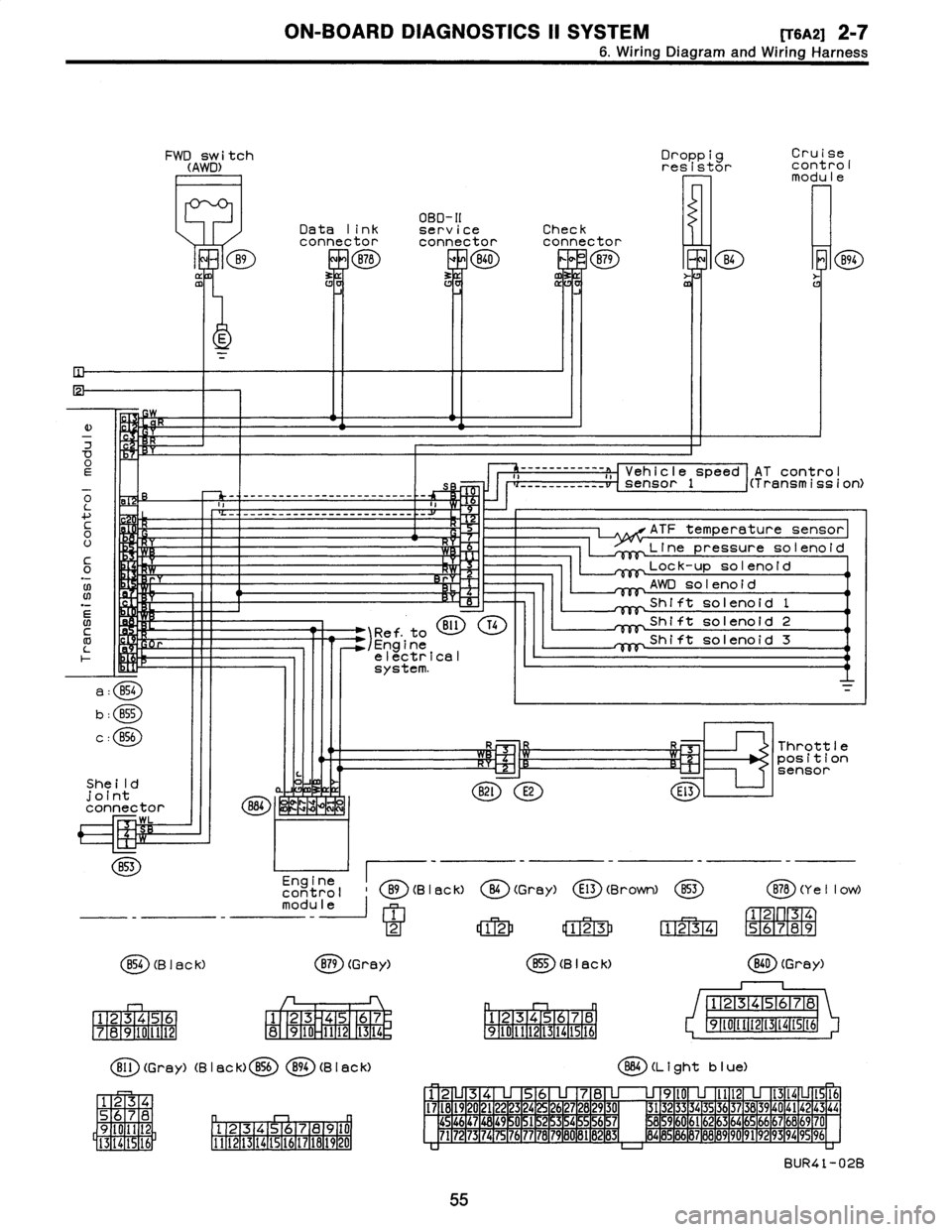
6
.
Wiring
Diagram
and
Wiring
Harness
FWD
switch
(AWD)
B9
ffl
Droppig
Cruise
resistor
cont
rol
modu
le
OBD-II
Data
link
serviceCheck
connectorconnectorconnector
B78
ERB40
0
B79
m
B4
E
K
E
)
w
7
OEs
o
-
-
-
------------------
-
------
-
-
L
a
....
c
H
0
U
It
C
Y
0
.N
;W
Rr
06
N
BI1
T41
Ref
.
to
/Engine
electrical
system
.
a
:
B54
b
:
B55
c
:
856
She
ild
joint
connector
884
~
WK
LZIM
WL
B53
Engine
control
B9(B
I
ac
k)
module
1
2
854
(B
I
ac
k)
B79
(Grey)
1
23456
1
23
45
67
7
1
8
1
9101112
8
910
1112
1
13
1
14
r,
Bll
(Grey)
(B
I
ac
k)
B56894
(B
I
aCk)
34
S
78
D
q
Oil
2
9
Pl
.
12131415,91617
la19
110
I
5
16
1
3
14
1111121131141151161171161191201
AT
contro
I
------------
a
,,
Vehicle
speed
i(Transmission)
___
_____
__
__
sensor
1
ATF
temperature
sensor
Line
pressuresolenoid
Lock-up
solenoid
AWD
solenoid
Shift
solenoid
1
Shift
solenoid
2
Shift
solenoid
3
R3
Throttle
~-Cz'1
R~l
position
sensor
B2l
E2
El3
O
(Gray)
E13
(Brown)
853
B78
(Y
e
II
ow)
12
123
1234
56789
B55
(B
I
ack)
(
ED
(Grey)
12345678
12345678
9~011t213141St6
91111213141516
864
(L
i
ght
b
I
ue)
12
345678
9l0
lll21314
1516
I7l8l9
20
2122
23
24
2627282930
3132
3334
35
3637383940
4142
43
44
454647
1
48
1
49
~
0
1
51
2
15
3
15
4
~
5
1
56
15
7
8596061626364656667686970
7172
73
1
74
1
75
1
76
1
77
78
1
79
1
60
1
81
B
1
132
1
83d
8485
86
87888990
9192
93
94
9596
BUR41-02B
55
Page 86 of 2890

ON-BOARD
DIAGNOSTICS
11
SYSTEM
[T11aoj
2-7
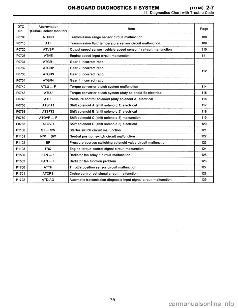
11
.
Diagnostics
Chart
with
Trouble
Code
DTC
No
.
Abbreviation
(Subaru
select
monitor)
Item
Page
P0705
ATRNG
Transmissionrange
sensor
circuit
malfunction
108
P0710
ATF
Transmission
fluid
temperature
sensor
circuit
malfunction
109
P0720
ATVSP
Output
speed
sensor
(vehicle
speed
sensor
1)
circuit
malfunction
110
P0725
ATNE
Engine
speed
input
circuit
malfunction
111
P0731
ATGR1
Gear
1
incorrect
ratio
P0732
ATGR2
Gear
2
incorrect
ratio
1
2
P0733
ATGR3
Gear
3
incorrect
ratio
1
P0734
ATGR4
Gear
4
incorrect
ratio
P0740
ATLU
-
F
Torque
converter
clutch
system
malfunction
114
P0743
ATLU
Torque
converter
clutch
system
(duty
solenoid
B)
electrical
115
P0748
ATPL
Pressure
control
solenoid
(duty
solenoid
A)
electrical
116
P0753
ATSFTi
Shift
solenoid
A
(shift
solenoid
1)
electrical
117
P0758
ATSFT2
Shift
solenoid
B
(shift
solenoid
2)
electrical
118
P0760
ATOVR
-
F
Shift
solenoid
C
(shift
solenoid
3)
malfunction
119
P0763
ATOVR
Shift
solenoid
C
(shift
solenoid
3)
electrical
120
P1100
ST
-
SW
Starter
switch
circuit
malfunction
121
P1101
N/P
-
SW
Neutral
position
switch
circuit
malfunction
122
P1102
BR
Pressure
sources
switching
solenoid
valve
circuit
malfunction
123
P1103
TRQ
Engine
torque
control
signal
circuit
malfunction
124
P1500
FAN
-
1
Radiator
fan
relay
1
circuit
malfunction
125
P1502
FAN
-
F
Radiator
fan
function
problem
126
P1700
ATTH
Throttle
position
sensor
circuit
malfunction
127
P1701
ATCRS
Cruise
control
set
signal
circuit
malfunction
128
P1702
ATDIAG
Automatic
transmission
diagnosis
inputsignal
circuit
malfunction
I
129
75
Page 119 of 2890
2_7
[T11AN0]
ON-BOARD
DIAGNOSTICS
II
SYSTEM
11
.
DiagnosticsChart
with
Trouble
Code
AN
:
DTC
P0705
-
-
TRANSMISSION
RANGE
SENSOR
CIRCUIT
MALFUNCTION
(ATRNG)
-
WIRING
DIAGRAM
:
a
:
Inhibitorb
:
(E)
switchc
:
TCM
8l2
a
:
B5i
b
:
O
c
:
B56
1234
56783456
12345678
12345678910
1
9
1
10
1
11
1
1
2r
[
74
1
9
1
10
1
11
1
1
21
9
(0111213141516
(1l
t
41
16(71
1920
82M0767
NOTE
:
For
the
diagnostic
procedure
on
transmission
range
sen-
sor
circuit
malfunction
(DTC
P0705),
refer
to
2-7
[T10AN0]*2
.
108
Page 120 of 2890
ON-BOARD
DIAGNOSTICS
II
SYSTEM
[Tiinooi
2-7
11
.
Diagnostics
Chart
with
Trouble
Code
AO
:
DTC
P0710
-
TRANSMISSION
FLUID
TEMPERATURE
SENSOR
CIRCUIT
MALFUNCTION
(ATF)
-
WIRING
DIAGRAM
:
a
c
:
B56
B11
TCM
c
:
856
8
1
5D
BIl
12
34
5678
1
23
456
7891
0
12
34
56
910
1112
1
11
1
1
21
13
1
14
1
15
1
16
1
17
1
18
[
19
12
9
1
78
910
1112
13161516
OBD0383
NOTE
:
For
the
diagnostic
procedure
on
transmission
fluid
tem-
perature
sensor
circuit
malfunction
(DTC
P0710),
refer
to
2-7
[T10AOO]*2
.
109
Page 125 of 2890
2-7
[T11AV0]
ON-BOARD
DIAGNOSTICS
11
SYSTEM
11
.
Diagnostics
Chart
with
Trouble
Code
AV
:
DTC
P0740
-
TORQUE
CONVERTER
CLUTCH
SYSTEM
MALFUNCTION
(ATLU
-
F)
-
WIRING
DIAGRAM
:
Automatic
transmission
Duty
ATF
Vehicle
solenoid
temperature
speed
B
sensor
sensorl
854
Brake
Throttle
b~
B55
1
Ii
t
positions
856
B11
T4
B53
TCM
Inhibitor
switch
N
00
0
a
t
~
3
1
B12
T3
Combination
meter
Speedometer
ECM
circuit
B84
e
:
B54
b
:
855
c
:
B56BI1B53812
O
123456
123456712345678910
81
1
234
5
67
8
9101112
1234
5678
910
11
12
13141516
3132
33
3435
363738394
0
4142
4344
6970
58596061626364L
111
9
1
10
1
11
1
12
1
13
1
14
1
15
11
6
789
101112
1
11
1
12
1
13
1
14
1
15
1
16
1
171819
20
1314
I
I6
1
2349
10
1112
8485
86
87888990
91
E3
1
0
-
4
1
95
96
12
B2M0587
NOTE
:
For
the
diagnostic
procedure
on
torque
converter
clutch
system
malfunction
(DTC
P0740),
referto
2-7
[T10AV0]*2
.
114
Page 130 of 2890
ON-BOARD
DIAGNOSTICS
II
SYSTEM
[T11BA0]
2-7
11
.
Diagnostics
Chart
with
Trouble
Code
BA
:
DTC
P0760
-
SHIFT
SOLENOID
C
(SHIFT
SOLENOID
3)
MALFUNCTION
(ATOVR
-
F)
-
WIRING
DIAGRAM
:
BIIT4
Automatic
transmission
4
S
JTM
Shift
solenoid
1
Shift
solenoid
2
Shift
solenoid
3
TCM
Inhibitor
B12
T3
-switch
PRND321
4
000000C
--------------
b
;
c
:
b
:
C
;
"I
L
34
Liel-ml
I
nn
78
15
,11
F21[3
1
4
1
5
1
r6j[7
8
9
01112
416178
9
1
R
L911[111111~13114115116
2346
711+81V90
1314
6
1
00
1112
013D0613,1
NOTE
:
For
the
diagnostic
procedure
on
shift
solenoid
C
malfunc-
tion
(DTC
P0760),
refer
to
2-7
[T10BA0]*2
.
119