Page 220 of 2890
![SUBARU LEGACY 1996 Service Repair Manual
ON-BOARD
DIAGNOSTICS
11
SYSTEM
[T10A0]
2-7
10
.
Diagnostics
Chart
with
Trouble
Code
DTC
No
.
Abbreviation
(Subaru
select
monitor)Item
Page
P0500
VSP
Vehicle
speed
sensor
malfunction
1
P0505
I SUBARU LEGACY 1996 Service Repair Manual
ON-BOARD
DIAGNOSTICS
11
SYSTEM
[T10A0]
2-7
10
.
Diagnostics
Chart
with
Trouble
Code
DTC
No
.
Abbreviation
(Subaru
select
monitor)Item
Page
P0500
VSP
Vehicle
speed
sensor
malfunction
1
P0505
I](/manual-img/17/57433/w960_57433-219.png)
ON-BOARD
DIAGNOSTICS
11
SYSTEM
[T10A0]
2-7
10
.
Diagnostics
Chart
with
Trouble
Code
DTC
No
.
Abbreviation
(Subaru
select
monitor)Item
Page
P0500
VSP
Vehicle
speed
sensor
malfunction
'1
P0505
ISC
Idle
control
system
malfunction
`1
P0506
ISC
-
L
Idle
control
system
RPM
lower
than
expected
'1
P0507
ISC
-
H
Idle
control
system
RPM
higher
than
expected
'1
P0600
-
Serial
communication
link
malfunction
`1
P0601
RAM
Internal
control
module
memory
check
sum
error
'1
P0703
ATBRK
Brake
switch
input
malfunction
'1
P0705
ATRNG
Transmissionrange
sensor
circuit
malfunction
`1
P0710
ATF
Transmission
fluid
temperature
sensor
circuit
malfunction
'1
P0720
ATVSP
Output
speed
sensor
(vehicle
speed
sensor
1)
circuit
malfunction
'1
P0725
ATNE
Engine
speed
input
circuit
malfunction
'1
P0731
ATGR1
Gear
1
incorrect
ratio
P0732
ATGR2
Gear
2
incorrect
ratio
"
1
P0733
ATGR3
Gear
3
incorrect
ratio
P0734
ATGR4
Gear
4
incorrect
ratio
P0740
ATLU
-
F
Torque
converter
clutch
system
malfunction
1
P0743
ATLU
Torque
converter
clutch
system
electrical
*1
P0748
ATPL
Pressure
control
solenoid
electrical
'1
P0753
ATSFTi
Shift
solenoid
A
electrical
`1
P0758
ATSFT2
Shift
solenoid
B
electrical
'1
P0760
ATOVR
-
F
Shift
solenoid
C
malfunction
'1
P0763
ATOVR
Shift
solenoid
C
electrical
'1
P1100
ST-SW
Starter
switch
circuit
malfunction
'1
P1101
N/P
-
SW
Neutral
position
switch
circuit
malfunction
[MT
vehicles]
'1
P1101
N/P
-
SW
Neutral
position
switch
circuit
malfunction
[AT
vehicles]
1
P1102
BR
Pressure
sources
switching
solenoid
valve
circuit
malfunction
'1
P1103
TRQ
Engine
torque
control
signal
circuit
malfunction
`1
P1400
PCVSOL
Fueltank
pressure
control
solenoid
valve
circuit
malfunction
38
P1401
PCV
-
FFueltank
pressure
control
system
function
problem
44
P1402
FIVL
Fuel
level
sensor
circuit
malfunction
46
P1500
FAN
-
1
Radiator
fan
relay
1
circuit
malfunction
'1
P1502
FAN
-
F
Radiator
fan
function
problem
'1
P1700
ATTH
Throttle
position
sensor
circuit
malfunction
for
automatic
transmission
'1
P1701
ATCRS
Cruise
control
set
signal
circuit
malfunction
for
automatic
transmission
'1
P1702
ATDIAG
Automatic
transmission
diagnosis
inputsignal
circuit
malfunction
'1
P0461'2
EXERR22
Fuel
level
sensor
circuit
range/performance
problem
56
"1
:
<
Ref
.
to
2-7
[T11A0]
.*4
>
'2
:
Only
OBD-II
general
scan
tool
displays
DTC
.
Page 269 of 2890
![SUBARU LEGACY 1996 Service Repair Manual 6-3
[Dso2]
WIRING
DIAGRAM
6
.
Wiring
Diagram
a
:
B54
b
:
BSS
c
:
B56
Transmission
:control
module
853
Shield
joint
connector
Lz7-
E3
822
E2821
-(California
model)
GEB3
Mass
aIr
flow
sensor SUBARU LEGACY 1996 Service Repair Manual 6-3
[Dso2]
WIRING
DIAGRAM
6
.
Wiring
Diagram
a
:
B54
b
:
BSS
c
:
B56
Transmission
:control
module
853
Shield
joint
connector
Lz7-
E3
822
E2821
-(California
model)
GEB3
Mass
aIr
flow
sensor](/manual-img/17/57433/w960_57433-268.png)
6-3
[Dso2]
WIRING
DIAGRAM
6
.
Wiring
Diagram
a
:
B54
b
:
BSS
c
:
B56
Transmission
:control
module
853
Shield
joint
connector
Lz7-
E3
822
E2821
-(California
model)
GEB3
Mass
aIr
flow
sensor
C
:
i14
il
B36
Comb
i
net
i
on
~?+
BRBR
meter
B76
Test
mode
connector
8l2
Inhibitorswitch
(
&
CD
Transmission
4
Vehicle
l
speed
-
sensor
1
B84
19
Engine
control
module
(
ED
~i
gnitor
B79
~
Chec
k
connector
(
9
)
.
eta
link
connector
S
.
M
.
J
.
[Refer
to
foldout
page
.]
OBD-II
B40
B97
R1
R(5R57
~8
Service
R
,EjeRO
FueI
pump
&
connector
1
-fuel
gauge
module
B76
(GreeN
853B3(G
ray)
Bl3
(Gray)
R58
R57878
(Ye
II
ow)
854
B
lack)
nT
456
4567856789
789012
1234
12345
123456
812
(Gray)
Bll
(Gray)
82l
(L
I
ght
i
14879
(Gray)
822
CL
1
ght
855
(B
I
ac
k)840
(Gray)
gray)
gray)
1234
1234
5678
12345678
7
8
1
9
1
10
1
11
1
124
12345678910111213
8
9
0
l
2
3l4
3l41S16
9
OL31123~ISlb
91001213141516
856
(B
I
ac
k)
i1
B
I
ac
k>
BB4
(L
(
ght
b
I
ue)
12
34
U
56
U
78
UU
9t0
U
1112
U
13141J1
516
1718
1
19
1
20
1
21
1
2223242S
I
26
27282930
3132
1
33
1
34
1
35
1
36
3738
39
40
4142
4344
11
1121314
5
6
78
9
l
01
2
3
456
7
8
9
l0
45
1
46
1
47
1
48
1
49
50
5152
1
53
1
54
1
55
1
56
1
57
1
58
5960
6162
636465
66
6768
64
70
11l2
t
3
(4151617
l8l9
20
l1
1
12
1
l3
1
14
1
15
1
16
1
1
7l8l9
20
2122
7172
7374
75767778
74
B0
8182
3
84
B58687888990
9192
9394
95
96
BUR04-03C
4
Page 503 of 2890

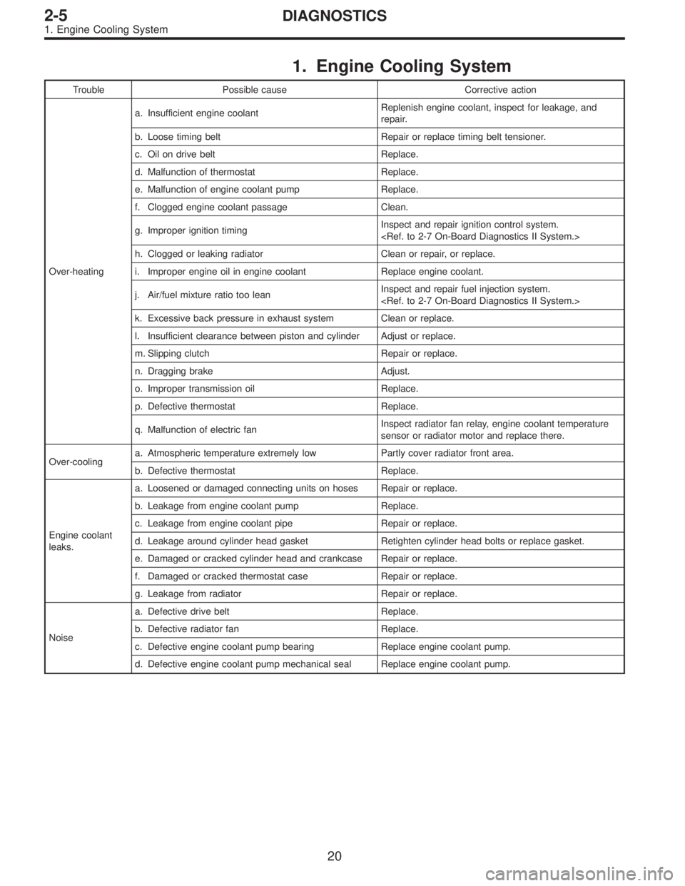
1. Engine Cooling System
Trouble Possible cause Corrective action
Over-heatinga. Insufficient engine coolantReplenish engine coolant, inspect for leakage, and
repair.
b. Loose timing belt Repair or replace timing belt tensioner.
c. Oil on drive belt Replace.
d. Malfunction of thermostat Replace.
e. Malfunction of engine coolant pump Replace.
f. Clogged engine coolant passage Clean.
g. Improper ignition timingInspect and repair ignition control system.
h. Clogged or leaking radiator Clean or repair, or replace.
i. Improper engine oil in engine coolant Replace engine coolant.
j. Air/fuel mixture ratio too leanInspect and repair fuel injection system.
k. Excessive back pressure in exhaust system Clean or replace.
l. Insufficient clearance between piston and cylinder Adjust or replace.
m. Slipping clutch Repair or replace.
n. Dragging brake Adjust.
o. Improper transmission oil Replace.
p. Defective thermostat Replace.
q. Malfunction of electric fanInspect radiator fan relay, engine coolant temperature
sensor or radiator motor and replace there.
Over-coolinga. Atmospheric temperature extremely low Partly cover radiator front area.
b. Defective thermostat Replace.
Engine coolant
leaks.a. Loosened or damaged connecting units on hoses Repair or replace.
b. Leakage from engine coolant pump Replace.
c. Leakage from engine coolant pipe Repair or replace.
d. Leakage around cylinder head gasket Retighten cylinder head bolts or replace gasket.
e. Damaged or cracked cylinder head and crankcase Repair or replace.
f. Damaged or cracked thermostat case Repair or replace.
g. Leakage from radiator Repair or replace.
Noisea. Defective drive belt Replace.
b. Defective radiator fan Replace.
c. Defective engine coolant pump bearing Replace engine coolant pump.
d. Defective engine coolant pump mechanical seal Replace engine coolant pump.
20
2-5DIAGNOSTICS
1. Engine Cooling System
Page 548 of 2890
G6M0095
16. Main Relay
A: REMOVAL AND INSTALLATION
1) Disconnect battery ground cable.
B5M0024A
2) Remove lower cover and then disconnect connectors.
3) Lower transmission control module.
4) Remove the front pillar lower trim.
5) Remove fuse box mounting nuts.
6) Lower fuse box.
7) Remove fuse box mounting bracket.
G2M0438
8) Remove screw which retains bracket of main relay�1
and fuel pump relay�2.
9) Disconnect connector from main relay.
G2M0438
10) Installation is in the reverse order of removal.
�
1Main relay
�
2Fuel pump relay
30
2-7SERVICE PROCEDURE
16. Main Relay
Page 549 of 2890
G6M0095
17. Fuel Pump Relay
A: REMOVAL AND INSTALLATION
1) Disconnect battery ground cable.
B5M0024A
2) Remove lower cover and then disconnect connectors.
3) Lower transmission control module.
4) Remove the front pillar lower trim.
5) Remove fuse box mounting nuts.
6) Lower fuse box.
7) Remove fuse box mounting bracket.
G2M0438
8) Remove fuel pump relay from main relay and fuel pump
relay mounting bracket.
9) Disconnect connector from fuel pump relay.
G2M0438
10) Installation is in the reverse order of removal.
�
1Main relay
�
2Fuel pump relay
31
2-7SERVICE PROCEDURE
17. Fuel Pump Relay
Page 562 of 2890
G2M0345
3. Fuel Tank
A: REMOVAL
1) Release fuel pressure.
2) Drain fuel from fuel tank.
G2M0382
3) Remove rear exhaust pipe.
(1) Lift-up the vehicle.
(2) Separate rear exhaust pipe from center exhaust
pipe.
(3) Separate rear exhaust pipe from muffler.
(4) Remove bracket from rubber cushion, and remove
exhaust pipe.
NOTE:
To facilitate the removal of parts, apply a coat of SUBARU
CRC5-56 (Part No. 004301003)
G2M0384
4) Remove muffler assembly.
NOTE:
To facilitate the removal of parts, apply a coat of SUBARU
CRC5-56 (Part No. 004301003)
G3M0059
5) Remove rear differential assembly. (AWD model)
(1) Remove rear axle shafts from rear differential
assembly.
(2) Remove rear differential front cover.
(3) Remove propeller shaft.
(4) Remove lower differential bracket.
(5) Set transmission jack under rear differential.
(6) Remove bolts which install rear differential onto
rear crossmember.
13
2-8SERVICE PROCEDURE
3. Fuel Tank
Page 591 of 2890

B2M0173A
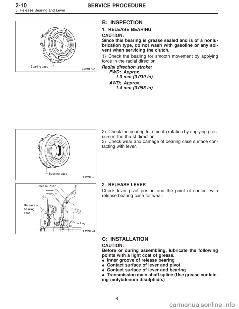
B: INSPECTION
1. RELEASE BEARING
CAUTION:
Since this bearing is grease sealed and is of a nonlu-
brication type, do not wash with gasoline or any sol-
vent when servicing the clutch.
1) Check the bearing for smooth movement by applying
force in the radial direction.
Radial direction stroke:
FWD; Approx.
1.0 mm (0.039 in)
AWD; Approx.
1.4 mm (0.055 in)
G2M0240
2) Check the bearing for smooth rotation by applying pres-
sure in the thrust direction.
3) Check wear and damage of bearing case surface con-
tacting with lever.
G2M0241
2. RELEASE LEVER
Check lever pivot portion and the point of contact with
release bearing case for wear.
C: INSTALLATION
CAUTION:
Before or during assembling, lubricate the following
points with a light coat of grease.
�Inner groove of release bearing
�Contact surface of lever and pivot
�Contact surface of lever and bearing
�Transmission main shaft spline (Use grease contain-
ing molybdenum disulphide.)
6
2-10SERVICE PROCEDURE
3. Release Bearing and Lever
Page 592 of 2890

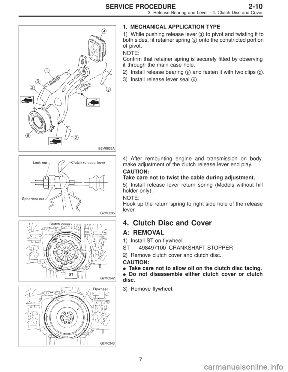
B2M0633A
1. MECHANICAL APPLICATION TYPE
1) While pushing release lever�
3to pivot and twisting it to
both sides, fit retainer spring�
5onto the constricted portion
of pivot.
NOTE:
Confirm that retainer spring is securely fitted by observing
it through the main case hole.
2) Install release bearing�
6and fasten it with two clips�2.
3) Install release lever seal�
4.
G2M0235
4) After remounting engine and transmission on body,
make adjustment of the clutch release lever end play.
CAUTION:
Take care not to twist the cable during adjustment.
5) Install release lever return spring (Models without hill
holder only).
NOTE:
Hook up the return spring to right side hole of the release
lever.
G2M0242
4. Clutch Disc and Cover
A: REMOVAL
1) Install ST on flywheel.
ST 498497100 CRANKSHAFT STOPPER
2) Remove clutch cover and clutch disc.
CAUTION:
�Take care not to allow oil on the clutch disc facing.
�Do not disassemble either clutch cover or clutch
disc.
G2M0243
3) Remove flywheel.
7
2-10SERVICE PROCEDURE
3. Release Bearing and Lever - 4. Clutch Disc and Cover