Page 1845 of 2890
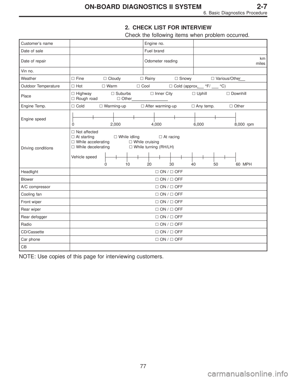
2. CHECK LIST FOR INTERVIEW
Check the following items when problem occurred.
Customer’s name Engine no.
Date of sale Fuel brand
Date of repair Odometer readingkm
miles
Vin no.
Weather�Fine�Cloudy�Rainy�Snowy�Various/Other
Outdoor Temperature�Hot�Warm�Cool�Cold (approx.°F/°C)
Place�Highway�Suburbs�Inner City�Uphill�Downhill
�Rough road�Other
Engine Temp.�Cold�Warming-up�After warming-up�Any temp.�Other
Engine speed
0 2,000 4,000 6,000 8,000 rpm
Driving conditions�Not affected
�At starting�While idling�At racing
�While accelerating�While cruising
�While decelerating�While turning (RH/LH)
Vehicle speed
0 102030405060MPH
Headlight�ON /�OFF
Blower�ON /�OFF
A/C compressor�ON /�OFF
Cooling fan�ON /�OFF
Front wiper�ON /�OFF
Rear wiper�ON /�OFF
Rear defogger�ON /�OFF
Radio�ON /�OFF
CD/Cassette�ON /�OFF
Car phone�ON /�OFF
CB
NOTE: Use copies of this page for interviewing customers.
77
2-7ON-BOARD DIAGNOSTICS II SYSTEM
6. Basic Diagnostics Procedure
Page 2256 of 2890
5. CHECK SOURCES OF SIGNAL NOISE.
1) Check that the mobile phone, personal radio and other
wireless apparatus are correctly installed.
2) Check that the antenna and other possible noise
sources are distant enough from the sensor harness.
3) Check that the sealed wires of the front harness sensor
(in the engine room) are securely grounded.
4) Check that between ABS/TCS control module and the
rear sensor harness has the correct twist pitch.
Twist pitch:
25 mm (0.98 in) or less
6. CHECK HYDRAULIC UNIT OPERATIONS.
1) Operate the ABS sequence control and check that the
brake fluid pressure at the malfunctioning brake line
increases and decreases properly.
45
4-4bBRAKES
8. Diagnostics Chart with Trouble Code
Page 2380 of 2890
B4M0814A
8C6
CHECK GROUND CIRCUIT OF ABSCM.
Measure resistance between ABSCM and chassis ground.
: Connector & terminal
(F49) No. 1—GND
(F49) No. 55—GND
Is resistance less than 0.5Ω?
: Go to step8C7.
: Repair ABSCM ground harness.
8C7CHECK POOR CONTACT IN CONNEC-
TOR BETWEEN ABSCM AND ABS SEN-
SOR.
: Is there poor contact in connectors between
ABSCM and ABS sensor?
: Repair connector.
: Go to step8C8.
8C8
CHECK SOURCES OF SIGNAL NOISE.
: Is the car telephone or the wireless trans-
mitter properly installed?
: Go to next.
: Properly install the car telephone or the wireless
transmitter.
: Are noise sources (such as an antenna)
installed near the sensor harness?
: Install the noise sources apart from the sensor
harness.
: Go to step8C9.
40
4-4cBRAKES [ABS 5.3 TYPE]
8. Diagnostics Chart with Trouble Code
Page 2400 of 2890
B4M0838A
8G1
CHECK GROUND CIRCUIT OF ABSCM.
1) Turn ignition switch to OFF.
2) Disconnect connector from ABSCM.
3) Measure resistance between ABSCM and chassis
ground.
: Connector & terminal
(F49) No. 1—Chassis ground
(F49) No. 55—Chassis ground
Is resistance less than 0.5Ω?
: Go to step8G2.
: Repair ABSCM ground harness.
8G2CHECK POOR CONTACT IN CONNEC-
TORS BETWEEN BATTERY, IGNITION
SWITCH AND ABSCM.
: Is there poor contact in connectors between
battery, ignition switch and ABSCM?
: Repair connector.
: Go to step8G3.
8G3
CHECK SOURCES OF SIGNAL NOISE.
: Is the car telephone or the wireless trans-
mitter properly installed?
: Go to next.
: Properly install the car telephone or the wireless
transmitter.
: Are noise sources (such as an antenna)
installed near the sensor harness?
: Install the noise sources apart from the sensor
harness.
: Go to step8G4.
60
4-4cBRAKES [ABS 5.3 TYPE]
8. Diagnostics Chart with Trouble Code
Page 2485 of 2890

B4M0922
10L1CHECK OUTPUT OF ABS SENSOR
USING SELECT MONITOR.
Read the ABS sensor output corresponding to the faulty
system in the select monitor function mode.
NOTE:
The select monitor display shows that the front right wheel
is rotating at 30 km/h.
: Does the speed indicated on the display
change in response to the speedometer
reading during acceleration/deceleration
when the steering wheel is in the straight-
ahead position?
: Go to step10L2.
: Go to step10L3.
10L2CHECK POOR CONTACT IN CONNEC-
TOR BETWEEN ABSCM AND ABS SEN-
SOR.
: Is there poor contact in connectors between
ABSCM and ABS sensor?
: Repair connector.
: Go to step10L3.
10L3
CHECK SOURCES OF SIGNAL NOISE.
: Is the car telephone or the wireless trans-
mitter properly installed?
: Go to next.
: Properly install the car telephone or the wireless
transmitter.
: Are noise sources (such as an antenna)
installed near the sensor harness?
: Install the noise sources apart from the sensor
harness.
: Go to step10L4.
145
4-4cBRAKES [ABS 5.3 TYPE]
10. Diagnostics Chart with Select Monitor
Page 2491 of 2890
10L13
CHECK SOURCES OF SIGNAL NOISE.
: Is the car telephone or the wireless trans-
mitter properly installed?
: Go to next.
: Properly install the car telephone or the wireless
transmitter.
: Are noise sources (such as an antenna)
installed near the sensor harness?
: Install the noise sources apart from the sensor
harness.
: Go to step10L14.
B4M1038A
10L14
CHECK SHIELD CIRCUIT.
1) Connect all connectors.
2) Measure resistance between shield connector and
chassis ground.
: Trouble code/Connector & terminal
22/(B100) No. 11—Chassis ground
24/(B100) No. 2—Chassis ground
26/(P1) No. 8—Chassis ground
28/(P1) No. 3—Chassis ground
Is resistance less than 0.5Ω?
: Go to step10L15.
: Repair shield harness.
151
4-4cBRAKES [ABS 5.3 TYPE]
10. Diagnostics Chart with Select Monitor
Page 2523 of 2890
B4M0838A
10V1
CHECK GROUND CIRCUIT OF ABSCM.
1) Turn ignition switch to OFF.
2) Disconnect connector from ABSCM.
3) Measure resistance between ABSCM and chassis
ground.
: Connector & terminal
(F49) No. 1—Chassis ground
(F49) No. 55—Chassis ground
Is resistance less than 0.5Ω?
: Go to step10V2.
: Repair ABSCM ground harness.
10V2CHECK POOR CONTACT IN CONNEC-
TORS BETWEEN BATTERY, IGNITION
SWITCH AND ABSCM.
: Is there poor contact in connectors between
battery, ignition switch and ABSCM?
: Repair connector.
: Go to step10V3.
10V3
CHECK SOURCES OF SIGNAL NOISE.
: Is the car telephone or the wireless trans-
mitter properly installed?
: Go to next.
: Properly install the car telephone or the wireless
transmitter.
: Are noise sources (such as an antenna)
installed near the sensor harness?
: Install the noise sources apart from the sensor
harness.
: Go to step10V4.
183
4-4cBRAKES [ABS 5.3 TYPE]
10. Diagnostics Chart with Select Monitor
 Check that the mobile phone, personal radio and other
wireless apparatus are correctly installed.
2) Check that the antenna and other possible noise
sources are di")
 No. 1—GND
(F49) No. 55—GND
Is resistance less than 0.5Ω?
: Go to ste")
 Turn ignition switch to OFF.
2) Disconnect connector from ABSCM.
3) Measure resistance between ABSCM and chassis
ground.
: Connector & terminal
(F49) No.")

 Turn ignition switch to OFF.
2) Disconnect connector from ABSCM.
3) Measure resistance between ABSCM and chassis
ground.
: Connector & terminal
(F49) No")