Page 1497 of 2890
B5M0413
19. Rear Spoiler (4 Door Sedan 2500 cc
GT model only)
A: REMOVAL AND INSTALLATION
1) Open trunk lid.
2) Disconnect high-mount stop light connector located
inside the trunk lid.
3) Remove rubber caps.
B5M0414
4) Remove rear spoiler mounting nuts.
CAUTION:
When removing nuts, be careful not to drop them
inside rear gate.
5) Installation is in the reverse order of removal.
Tightening torque:
7.4±2.0 N⋅m (0.75±0.2 kg-m, 5.4±1.4 ft-lb)
B5M0305
20. Roof Spoiler (Station Wagon 2500
cc GT model only)
A: REMOVAL AND INSTALLATION
1) Open rear gate and remove rear gate trim upper and
side.
2) Remove high-mount stop light.
B5M0415A
3) Remove plastic caps and harness covers.
62
5-1SERVICE PROCEDURE
19. Rear Spoiler (4 Door Sedan 2500 cc GT model only) - 20. Roof Spoiler (Station Wagon 2500 cc GT model only)
Page 1550 of 2890
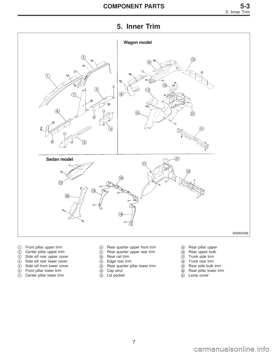
5. Inner Trim
B5M0036B
�1Front pillar upper trim
�
2Center pillar upper trim
�
3Side sill rear upper cover
�
4Side sill rear lower cover
�
5Side sill front lower cover
�
6Front pillar lower trim
�
7Center pillar lower trim�
8Rear quarter upper front trim
�
9Rear quarter upper rear trim
�
10Rear rail trim
�
11Edge rear trim
�
12Rear quarter pillar lower trim
�
13Cap strut
�
14Lid pocket�
15Rear pillar upper
�
16Rear upper bulk
�
17Trunk side trim
�
18Trunk rear trim
�
19Rear side bulk trim
�
20Rear pillar lower trim
�
21Lamp cover
7
5-3COMPONENT PARTS
5. Inner Trim
Page 1655 of 2890
, 100 minutes (AT)
Cold cranking ampere 430 amperes (MT), 490 amperes (AT)
Fuse10 A, 15 A, 20 A
Combination
meterSpeedometer")
1. Body Electrical
A: SPECIFICATIONS
BatteryReserve capacity 82 minutes (MT), 100 minutes (AT)
Cold cranking ampere 430 amperes (MT), 490 amperes (AT)
Fuse10 A, 15 A, 20 A
Combination
meterSpeedometer Electric pulse type
Tachometer Electric impulse type
Water temperature gauge Thermistor cross coil type
Fuel gauge Resistance cross coil type
Charge indicator light 12 V—1.4 W
Brake fluid level warning/parking brake indicator light 12 V—1.4 W
AT oil temperature warning light (AWD only) 12 V—1.4 W
A.B.S. warning light 12 V—1.4 W
CHECK ENGINE warning light
(Malfunction indicator lamp)12 V—1.4 W
Oil pressure warning light 12 V—1.4 W
AIRBAG system warning light 12 V—1.4 W
Low fuel warning light 12 V—3W
FWD indicator light 12 V—1.4 W
TCS warning light 12 V—1.4 W
TCS indicator light 12 V—1.4 W
Turn signal indicator light 12 V—1.4 W (2 pieces)
Seat belt warning light 12 V—1.4 W
Door open warning light 12 V—1.4 W
Headlight beam indicator light 12 V—1.4 W
Meter illumination light12 V—3 W (2 pieces)
12 V—3.4 W (4 pieces)
Headlight 12 V—60/55 W (Halogen)
Front clearance light 12 V—5W
Turn signal lightFront 12 V—21 W
Rear 12 V—21 W
Tail/Stop light 12 V—5/21 W
Back-up light 12 V—21 W
High-mount stop light12 V—18 W (SEDAN), 12 V—13 W
(WAGON)
License plate light 12 V—5W
Room light 12 V—8W
Trunk room light (SEDAN) 12 V—5W
Luggage room light (WAGON) 12 V—5W
Spot light 12 V—8 W (2 pieces)
Glove box light 12 V—3.4 W
Ash tray illumination light 12 V—1.7 W
Selector lever illumination light (AT model) 12 V—1.7 W
2
6-2SPECIFICATIONS
1. Body Electrical
Page 1670 of 2890
 Remove rear trim.
2) Disconnect connector from rear combination light.
3) Remove nuts which secure rea")
B6M0055A
B6M0056A
5. Stop and Tail Light
A: REMOVAL AND INSTALLATION
1. REAR COMBINATION LIGHT
1) Remove rear trim.
2) Disconnect connector from rear combination light.
3) Remove nuts which secure rear combination light.
Tightening torque:
2.5±0.5 N⋅m (0.25±0.05 kg-m, 1.8±0.4 ft-lb)
4) Attach adhesive cloth tape to body area around rear
combination light.
5) Using a standard screwdriver, carefully pry rear combi-
nation light off and away from the vehicle.
CAUTION:
�Do not pry rear combination light forcefully as this
may scratch vehicle body.
�Remove all traces of adhesive tape from body before
installation.
�Attach butyl rubber tape to back of rear combination
light before installing rear combination light on body
for sealing purposes.
B6M0057A
B6M0058A
2. REAR FINISHER
1) Remove trunk lid trim (SEDAN) or rear gate trim
(WAGON).
2) Disconnect connectors from rear finisher.
3) Remove rear wiper motor (WAGON).
4) Remove nuts which secure rear finisher.
Tightening torque:
2.5±0.5 N⋅m (0.25±0.05 kg-m, 1.8±0.4 ft-lb)
5) Attach adhesive cloth tape to body area around rear
finisher.
6) Using a standard screwdriver, carefully pry rear finisher
off and away from the vehicle.
CAUTION:
Do not pry rear finisher forcefully as this may scratch
vehicle body.
14
6-2SERVICE PROCEDURE
5. Stop and Tail Light
Page 1676 of 2890
![SUBARU LEGACY 1996 Service Repair Manual 7. Back-up Light
A: REMOVAL AND INSTALLATION
1. BACK-UP LIGHT
Refer to 6-2 [W5A2] as for removal and installation of rear
finisher.
2. BACK-UP LIGHT SWITCH (MT MODEL)
Refer to 3-1 [W2B1 (AWD) or W3A0](/manual-img/17/57433/w960_57433-1675.png "SUBARU LEGACY 1996 Service Repair Manual 7. Back-up Light
A: REMOVAL AND INSTALLATION
1. BACK-UP LIGHT
Refer to 6-2 [W5A2] as for removal and installation of rear
finisher.
2. BACK-UP LIGHT SWITCH (MT MODEL)
Refer to 3-1 [W2B1 (AWD) or W3A0")
7. Back-up Light
A: REMOVAL AND INSTALLATION
1. BACK-UP LIGHT
Refer to 6-2 [W5A2] as for removal and installation of rear
finisher.
2. BACK-UP LIGHT SWITCH (MT MODEL)
Refer to 3-1 [W2B1 (AWD) or W3A0 (FWD)] as for removal
and installation of back-up light switch.
3. INHIBITOR SWITCH (AT MODEL)
Refer to 3-2 [W4A3] as for removal and installation of
inhibitor switch (R position switch).
B: INSPECTION
1. INHIBITOR SWITCH (AT MODEL)
Refer to 3-2 [W2B2] as for inspection of inhibitor switch.
B6M0068
8. Room Light and Door Switch
A: REMOVAL AND INSTALLATION
1. ROOM LIGHT
1) Pry room light lens off using a screwdriver.
2) Remove screws which secure room light body.
3) Remove room light body while disconnecting connector.
B6M0345A
2. TRUNK ROOM LIGHT (SEDAN)
1) Turn trunk room light body by hand and remove it from
rear shelf panel.
2) Disconnect connector of trunk room light.
B6M0069
3. LUGGAGE ROOM LIGHT (WAGON)
1) Pry luggage room light lens off using a screwdriver.
2) Remove screws which secure luggage room light body.
3) Remove luggage room light body while disconnecting
connector.
20
6-2SERVICE PROCEDURE
7. Back-up Light - 8. Room Light and Door Switch
Page 1677 of 2890
![SUBARU LEGACY 1996 Service Repair Manual 7. Back-up Light
A: REMOVAL AND INSTALLATION
1. BACK-UP LIGHT
Refer to 6-2 [W5A2] as for removal and installation of rear
finisher.
2. BACK-UP LIGHT SWITCH (MT MODEL)
Refer to 3-1 [W2B1 (AWD) or W3A0](/manual-img/17/57433/w960_57433-1676.png "SUBARU LEGACY 1996 Service Repair Manual 7. Back-up Light
A: REMOVAL AND INSTALLATION
1. BACK-UP LIGHT
Refer to 6-2 [W5A2] as for removal and installation of rear
finisher.
2. BACK-UP LIGHT SWITCH (MT MODEL)
Refer to 3-1 [W2B1 (AWD) or W3A0")
7. Back-up Light
A: REMOVAL AND INSTALLATION
1. BACK-UP LIGHT
Refer to 6-2 [W5A2] as for removal and installation of rear
finisher.
2. BACK-UP LIGHT SWITCH (MT MODEL)
Refer to 3-1 [W2B1 (AWD) or W3A0 (FWD)] as for removal
and installation of back-up light switch.
3. INHIBITOR SWITCH (AT MODEL)
Refer to 3-2 [W4A3] as for removal and installation of
inhibitor switch (R position switch).
B: INSPECTION
1. INHIBITOR SWITCH (AT MODEL)
Refer to 3-2 [W2B2] as for inspection of inhibitor switch.
B6M0068
8. Room Light and Door Switch
A: REMOVAL AND INSTALLATION
1. ROOM LIGHT
1) Pry room light lens off using a screwdriver.
2) Remove screws which secure room light body.
3) Remove room light body while disconnecting connector.
B6M0345A
2. TRUNK ROOM LIGHT (SEDAN)
1) Turn trunk room light body by hand and remove it from
rear shelf panel.
2) Disconnect connector of trunk room light.
B6M0069
3. LUGGAGE ROOM LIGHT (WAGON)
1) Pry luggage room light lens off using a screwdriver.
2) Remove screws which secure luggage room light body.
3) Remove luggage room light body while disconnecting
connector.
20
6-2SERVICE PROCEDURE
7. Back-up Light - 8. Room Light and Door Switch
Page 1678 of 2890
 Remove rubber boot of door switch.
2) Remove screw which secures door switch to body.
3) Remove door switch while disconnecting connector.
5. TRUNK ROOM LIGHT SWITCH (SEDAN)")
B6M0070A
4. DOOR SWITCH
1) Remove rubber boot of door switch.
2) Remove screw which secures door switch to body.
3) Remove door switch while disconnecting connector.
5. TRUNK ROOM LIGHT SWITCH (SEDAN)
Refer to 5-1 [W2A3] as for removal and installation of trunk
room light switch which is installed in trunk lid lock.
6. LUGGAGE ROOM LIGHT SWITCH (WAGON)
Refer to 5-2 [W3A2] as for removal and installation of lug-
gage room light switch which is installed in rear gate lock.
B6M0071
B: INSPECTION
1. DOOR SWITCH
Move switch and check continuity between terminal of door
switch and switch body.
Switch position Terminal Switch body
Open (ON)��
Push in (OFF)
B6M0072A
2. TRUNK ROOM LIGHT SWITCH (SEDAN)
Move switch and check continuity between terminals of
trunk room light switch.
Terminal
Switch position12
Open (ON)��
Push in (OFF)
B6M0073A
3. LUGGAGE ROOM LIGHT SWITCH (WAGON)
Move switch and check continuity between terminals of
luggage room light switch.
Terminal
Switch position12
Open (ON)��
Push in (OFF)
21
6-2SERVICE PROCEDURE
8. Room Light and Door Switch
Page 1710 of 2890
 Disconnect connector from speaker.
4) Remove screws which secure the speaker.
5) Remove door mount speaker.
3. REAR SPEAKER (SEDAN)
1) Remove rear seat cushion and rear backrest.
2) Remove")
B6M0162
3) Disconnect connector from speaker.
4) Remove screws which secure the speaker.
5) Remove door mount speaker.
3. REAR SPEAKER (SEDAN)
1) Remove rear seat cushion and rear backrest.
2) Remove left and right rear quarter trim panels.
3) Remove rear shelf trim panel.
4) Remove screws which secure speaker.
5) Remove speaker while disconnecting connector from
speaker.
4. REAR SPEAKER (WAGON)
1) Remove door trim panel.
2) Disconnect connector from speaker.
3) Remove screws which secure the speaker.
4) Remove speaker.
B6M0147A
5. POWER ANTENNA
1) Remove left side trunk trim (SEDAN), or left side rear
lower quarter trim (WAGON).
2) Remove special nut (SEDAN).
3) Remove bolt which secures power antenna.
4) Remove power antenna while disconnecting connector
and water drain hose.
B6M0149A
B: INSPECTION
1. POWER ANTENNA
1) Connect battery positive (+) terminal to terminal No. 3
and connect terminal No. 1 (SEDAN) or No. 6 (WAGON)
to ground. Ensure that antenna rod extends properly when
battery positive (+) terminal is connected to terminal No. 2
(SEDAN) or No. 4 (WAGON).
2) Ensure that antenna rod retracts properly when battery
positive (+) terminal is disconnected from terminal No. 2
(SEDAN) or No. 4 (WAGON).
46
6-2SERVICE PROCEDURE
20. Radio, Speaker and Antenna

A: REMOVAL AND INSTALLATION
1) Open trunk lid.
2) Disconnect high-mount stop light connector located
inside the trunk lid.
3) Remove rubbe")