Page 308 of 2890
G2M0088
6. Engine Oil Pressure
A: MEASUREMENT
1) Remove generator from bracket.
(1) Disconnect connector and terminal from generator.
G2M0089
(2) Remove V-belt cover.
(3) Loosen lock bolt and slider bolt, and remove V-belt
for generator.
G2M0090
(4) Remove generator lock bolt.
(5) Remove bolt which install generator on bracket.
G2M0091
2) Disconnect connector from oil pressure switch.
3) Remove oil pressure switch from engine cylinder block.
7
2-2
6. Engine Oil Pressure
Page 309 of 2890
G2M0093
4) Connect oil pressure gauge hose to cylinder block.
5) Start the engine, and measure oil pressure.
Oil pressure:
98 kPa (1.0 kg/cm
2,14 psi) or more at 800 rpm
294 kPa (3.0 kg/cm2, 43 psi) or more at 5,000 rpm
CAUTION:
�If oil pressure is out of specification, check oil
pump, oil filter and lubrication line.
�If oil pressure warning light is turned ON and oil
pressure is in specification, replace oil pressure
switch.
NOTE:
The specified data is based on an engine oil temperature
of 80°C (176°F).
6) After measuring oil pressure, install oil pressure switch.
Tightening torque:
25±3 N⋅m (2.5±0.3 kg-m, 18.1±2.2 ft-lb)
7) Install generator and V-belt in the reverse order of
removal, and adjust the V-belt deflection.
8
2-2
6. Engine Oil Pressure
Page 312 of 2890

Squareness 2.5°, 1.9 mm (0.075 in)
Tension/spring height174.6—200.1 N
(17.8—20.4 kg, 39.2—45.0 lb)/36.0 mm (1.417 in)
405.0—458.0 N
(41.3—46.7 k")
Valve springFree length 44.05 mm (1.7342 in)
Squareness 2.5°, 1.9 mm (0.075 in)
Tension/spring height174.6—200.1 N
(17.8—20.4 kg, 39.2—45.0 lb)/36.0 mm (1.417 in)
405.0—458.0 N
(41.3—46.7 kg, 91.1—103.0 lb)/28.2 mm (1.110 in)
Cylinder
blockSurface warpage limit (mating with cylinder head) 0.05 mm (0.0020 in)
Surface grinding limit 0.1 mm (0.004 in)
Cylinder bore STDA 96.905—96.915 mm (3.8151—3.8155 in)
B 96.895—96.905 mm (3.8148—3.8151 in)
TaperSTD 0.015 mm (0.0006 in)
Limit 0.050 mm (0.0020 in)
Out-of-roundnessSTD 0.010 mm (0.0004 in)
Limit 0.050 mm (0.0020 in)
Piston clearanceSTD 0.010—0.030 mm (0.0004—0.0012 in)
Limit 0.050 mm (0.0020 in)
Enlarging (boring) limit 0.5 mm (0.020 in)
Piston Outer diameterSTDA 96.885—96.895 mm (3.8144—3.8148 in)
B 96.875—96.885 mm (3.8140—3.8144 in)
0.25 mm (0.0098 in)
OS97.115—97.145 mm (3.8234—3.8246 in)
0.50 mm (0.0197 in)
OS97.365—97.395 mm (3.8333—3.8344 in)
Piston pinStandard clearance between piston
pin and hole in pistonSTD 0.004—0.010 mm (0.0002—0.0004 in)
Limit 0.020 mm (0.0008 in)
Degree of fitPiston pin must be fitted into position with thumb at 20°C
(68°F).
Piston ringPiston ring gapTop ringSTD 0.20—0.35 mm (0.0079—0.0138 in)
Limit 1.0 mm (0.039 in)
Second
ringSTD 0.20—0.50 mm (0.0079—0.0197 in)
Limit 1.0 mm (0.039 in)
Oil ringSTD 0.20—0.70 mm (0.0079—0.0276 in)
Limit 1.5 mm (0.059 in)
Clearance between piston
ring and piston ring grooveTop ringSTD 0.040—0.080mm (0.0016—0.0031 in)
Limit 0.15 mm (0.0059 in)
Second
ringSTD 0.030—0.070 mm (0.0012—0.0028 in)
Limit 0.15 mm (0.0059 in)
Connecting
rodBend twist per 100 mm (3.94 in) in
lengthLimit 0.10 mm (0.0039 in)
Side clearanceSTD 0.070—0.330 mm (0.0028—0.0130 in)
Limit 0.4 mm (0.016 in)
Connecting
rod bearingOil clearanceSTD 0.015—0.045 mm (0.0006—0.0018 in)
Limit 0.05 mm (0.0020 in)
Thickness at center portionSTD 1.492—1.501 mm (0.0587—0.0591 in)
0.03 mm
(0.0012 in)
US1.510—1.513 mm (0.0594—0.0596 in)
0.05 mm
(0.0020 in)
US1.520—1.523 mm (0.0598—0.0600 in)
0.25 mm
(0.0098 in)
US1.620—1.623 mm (0.0638—0.0639 in)
Connecting
rod bushingClearance between piston pin and
bushingSTD 0—0.022 mm (0—0.0009 in)
Limit 0.030 mm (0.0012 in)
STD: Standard OS: Oversize US: Undersize
4
2-3SPECIFICATIONS AND SERVICE DATA
1. Engine
Page 317 of 2890
4. Cylinder Block
B2M0381A
�1Oil pressure switch
�
2Cylinder block (RH)
�
3Service hole plug
�
4Gasket
�
5Oil separator cover
�
6Water pipe
�
7Oil pump
�
8Front oil seal
�
9Rear oil seal
�
10O-ring
�
11Service hole cover
�
12Cylinder block (LH)
�
13Water pump
�
14Baffle plate
�
15Oil strainer stay
�
16Oil strainer�
17Gasket
�
18Oil pan
�
19Oil drain plug
�
20Gasket
�
21Oil filler pipe
Tightening torque: N⋅m (kg-m, ft-lb)
T1: 5 (0.5, 3.6)
T2: 6.4 (0.65, 4.7)
T3: 10 (1.0, 7)
T4: 25±2 (2.5±0.2, 18.1±1.4)
T5: 47±3 (4.8±0.3, 34.7±2.2)
T6: 69±7 (7.0±0.7, 50.6±5.1)
T7: First 12±2 (1.2±0.2, 8.7±1.4)
Second 12±2 (1.2±0.2, 8.7±1.4)
9
2-3COMPONENT PARTS
4. Cylinder Block
Page 325 of 2890
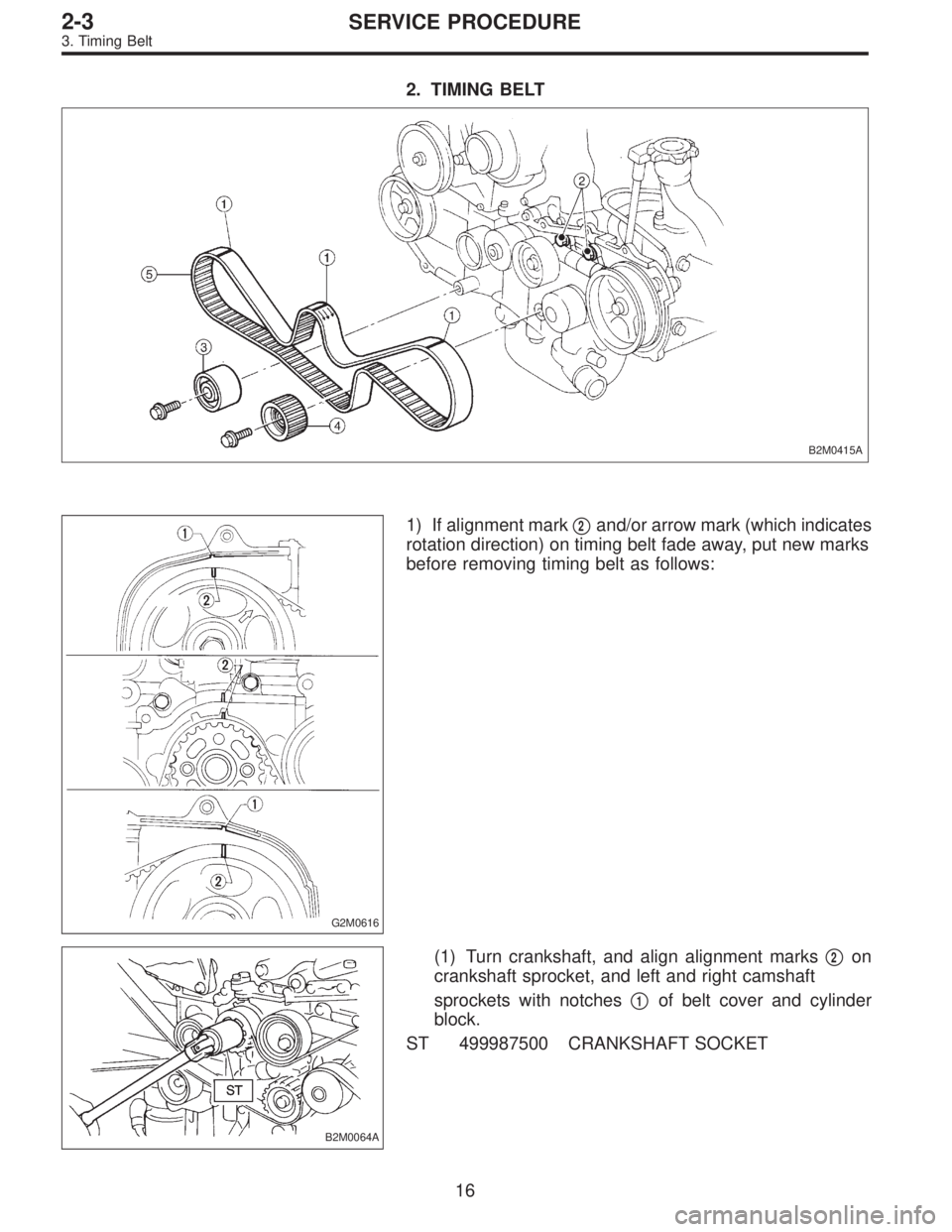
2. TIMING BELT
B2M0415A
G2M0616
1) If alignment mark�2and/or arrow mark (which indicates
rotation direction) on timing belt fade away, put new marks
before removing timing belt as follows:
B2M0064A
(1) Turn crankshaft, and align alignment marks�2on
crankshaft sprocket, and left and right camshaft
sprockets with notches�
1of belt cover and cylinder
block.
ST 499987500 CRANKSHAFT SOCKET
16
2-3SERVICE PROCEDURE
3. Timing Belt
Page 349 of 2890
2. CYLINDER HEAD
B2M0119A
1) Remove timing belt, camshaft sprocket and related
parts.
2) Remove oil level gauge guide attaching bolt (left hand
only) and oil level gauge guide.
B2M0120A
3) Remove cylinder head bolts in numerical sequence
shown in Figure.
CAUTION:
Leave bolts�
1and�3engaged by three or four threads
to prevent cylinder head from falling.
4) While tapping cylinder head with a plastic hammer,
separate it from cylinder block.
Remove bolts�
1and�3to remove cylinder head.
5) Remove cylinder head gasket.
CAUTION:
Do not scratch the mating surface of cylinder head and
cylinder block.
6) Similarly, remove right side cylinder head.
39
2-3SERVICE PROCEDURE
6. Cylinder Head
Page 358 of 2890
E: INSTALLATION
1. CYLINDER HEAD
B2M0119B
1) Install cylinder head and gaskets on cylinder block.
CAUTION:
Use new cylinder head gaskets.
B2M0120B
2) Tighten cylinder head bolts.
(1) Apply a coat of engine oil to washers and bolt
threads.
(2) Tighten all bolts to 29 N⋅m (3.0 kg-m, 22 ft-lb) in
numerical sequence.
Then tighten all bolts to 69 N⋅m (7.0 kg-m, 51 ft-lb) in
numerical sequence.
(3) Back off all bolts by 180°first; back them off by 180°
again.
(4) Tighten bolts�
1and�2to 34 N⋅m (3.5 kg-m, 25 ft-
lb).
(5) Tighten bolts�
3,�4,�5and�6to 15 N⋅m (1.5 kg-m,
11 ft-lb).
(6) Tighten all bolts by 80 to 90°in numerical
sequence.
CAUTION:
Do not tighten bolts more than 90°.
48
2-3SERVICE PROCEDURE
6. Cylinder Head
Page 360 of 2890
7. Cylinder Block
A: REMOVAL
1. RELATED PARTS
1) Remove timing belt, camshaft sprocket and related
parts.
2) Remove intake manifold and cylinder head.
2. OIL PUMP AND ENGINE COOLANT PUMP
B2M0124A
50
2-3SERVICE PROCEDURE
7. Cylinder Block
 Remove generator from bracket.
(1) Disconnect connector and terminal from generator.
G2M0089
(2) Remove V-belt cover.
(3) Loosen lock bolt and slider b")
 Connect oil pressure gauge hose to cylinder block.
5) Start the engine, and measure oil pressure.
Oil pressure:
98 kPa (1.0 kg/cm
2,14 psi) or more at 800 rpm
294 kPa (3.0 kg/cm2, 43 psi) o")

![SUBARU LEGACY 1996 Service Repair Manual 2. CYLINDER HEAD
B2M0119A
1) Remove timing belt, camshaft sprocket and related
parts.
<Ref. to 2-3 [W3A0].>
2) Remove oil level gauge guide attaching bolt (left hand
only) and oil level gauge guide.
B](/manual-img/17/57433/w960_57433-348.png "SUBARU LEGACY 1996 Service Repair Manual 2. CYLINDER HEAD
B2M0119A
1) Remove timing belt, camshaft sprocket and related
parts.
<Ref. to 2-3 [W3A0].>
2) Remove oil level gauge guide attaching bolt (left hand
only) and oil level gauge guide.
B")
 Install cylinder head and gaskets on cylinder block.
CAUTION:
Use new cylinder head gaskets.
B2M0120B
2) Tighten cylinder head bolts.
(1) Apply a coat of e")
![SUBARU LEGACY 1996 Service Repair Manual 7. Cylinder Block
A: REMOVAL
1. RELATED PARTS
1) Remove timing belt, camshaft sprocket and related
parts.
<Ref. to 2-3 [W3A0].>
2) Remove intake manifold and cylinder head.
<Ref. to 2-3 [W6A0].>
2. OI](/manual-img/17/57433/w960_57433-359.png "SUBARU LEGACY 1996 Service Repair Manual 7. Cylinder Block
A: REMOVAL
1. RELATED PARTS
1) Remove timing belt, camshaft sprocket and related
parts.
<Ref. to 2-3 [W3A0].>
2) Remove intake manifold and cylinder head.
<Ref. to 2-3 [W6A0].>
2. OI")