Page 1 of 2890
1-1
[s2o2]
SPECIFICATIONS
2
.
Station
Wagon
2
.
Station
Wagon
2
.
ENGINE
Engine
type
Horizontally
opposed,
liquid
cooled,
4-cylinder,
4-stroke
gasoline
engine
Valve
arrangement
Overhead
camshaft
type
Bore
x
Stroke
mm
(in)
96
.9
x75
.0(3
.815
x2
.953)
Displacement
cm3
(cu
in)
2,212
(135
.0)
Compression
ratio
9
.7
Firing
order
1-3-2-4
Idle
speed
at
Park/Neutral
position
rpm700
Maximum
output
kW
(HP)/rpm
101
(135)/5,400
Maximum
torque
N
.m
(kg-m,
ft-Ib)/rpm
190
(19
.4,140)/4,400
3
.
ELECTRICAL
Ignition
timing
atidling
speed
BTDC/rpm
20°/700
Spark
plug
Type
and
manufacturer
CHAMPION
:
RC10YC4
(Standard)
NGK
:
BKR6E-11
NIPPONDENSO
:
K20PR-U11
Generator
12V
-
85A
Battery
Reserve
capacity
min100
Cold
cranking
amperes
amp
.I
490
Page 12 of 2890
5-5b
[cioo]
COMPONENT
PARTS
1
.
SRS
Airbag
1
.
SRS
Airbag
I
T2
I
(2
T5
7
~9
i
T1
T3
T4
BSM0434A
1~
Combination
switch
ASSY
with
roll
connector
~2
TORXO
bolt
~3
Airbag
module
ASSY
(Driver)
~4
Airbag
module
ASSY
(Passenger)
~5
BRKT
B
Q6
BRKT
P
AB
07
BRKTSD
A
~s
TORXO
bolt
Airbag
control
module
~o
Protector
RH
Protector
LH
~2
Airbag
main
harness
Tightening
torque
:
N~m
(kg-m,
It-1b)
T1
:
1
.8
f
0
.5
(0
.18
:L
0
.05,1.3
:1
:
0
.4)
T2
:
2
.5±
0
.5
(0
.25±
0
.05,1
.8±
0
.4)
T3
:
4
.4
f
1
.5(0
.45
f
0
.15,
3
.3±
1
.1)
T4
:
7
.4±
0
.5
(0
.75
:L
0
.05,
5
.4
f
0
.4)
rs
:
10
t
z
(1.o
t
0
.2,
7
.2
:L
1
.4)
T6
:
32
f
10
(3
.3
:
:L
1
.0,
23
.9
f
7
.2)
2
o
lJ
T5
Page 42 of 2890

ON-BOARD
DIAGNOSTICS
II
SYSTEM
ITscas1
2-7
3
.
Diagnosis
System
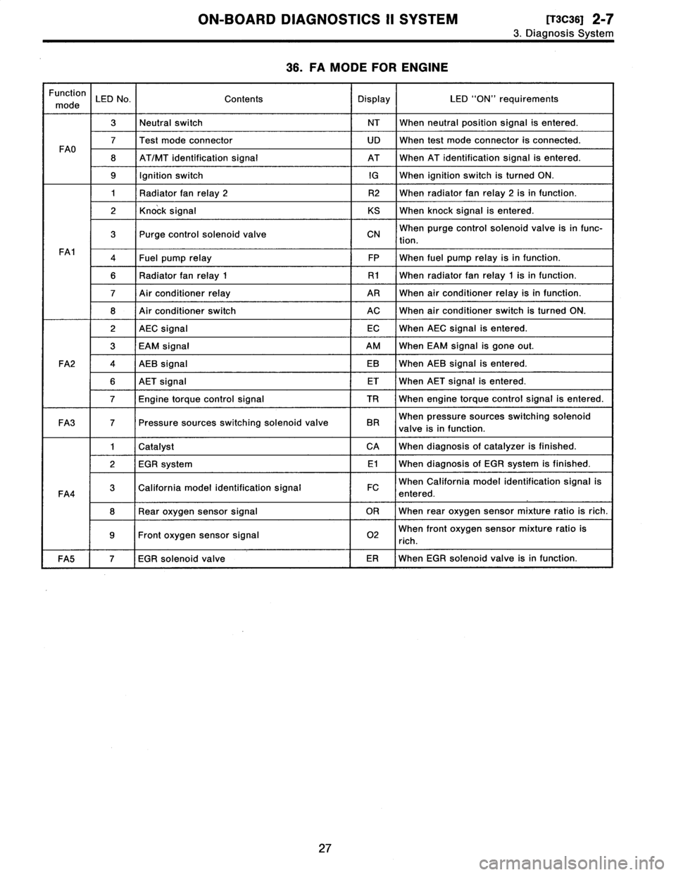
36
.
FA
MODE
FOR
ENGINE
Function
mode
LED
No
.
Contents
Display
LED
"ON"
requirements
3Neutral
switch
NT
When
neutralposition
signal
is
entered
.
7Test
mode
connector
UD
When
test
mode
connector
is
connected
.
FAO
8
AT/MT
identification
signal
AT
When
AT
identification
signal
is
entered
.
9
Ignition
switchIG
When
ignition
switch
is
turned
ON
.
1
Radiator
fan
relay
2
R2
When
radiator
fanrelay2
isin
function
.
2
Knock
signal
KS
When
knock
signal
is
entered
.
3
Purge
control
solenoid
valve
CNWhen
purge
control
solenoid
valve
is
in
func-
tion
.
FA1
4Fuel
pump
relay
FP
When
fuel
pump
relay
isin
function
.
6
Radiator
fanrelay
1
R1
When
radiator
fanrelay
1
isin
function
.
7
Air
conditioner
relay
ARWhen
air
conditioner
relay
isin
function
.
8
Air
conditioner
switch
ACWhen
air
conditioner
switch
is
turned
ON
.
2
AEC
signal
ECWhen
AEC
signal
is
entered
.
3
EAM
signal
AM
When
EAM
signal
is
gone
out
.
FA2
4
AEB
signal
EB
When
AEB
signal
is
entered
.
6
AET
signal
ET
When
AET
signal
is
entered
.
7
Engine
torque
control
signal
TR
When
engine
torque
control
signal
is
entered
.
FA3
7
Pressure
sources
switching
solenoid
valve
BR
When
pressure
sources
switching
solenoid
valve
is
in
function
.
1
Catalyst
CA
When
diagnosis
of
catalyzer
is
finished
.
2
EGR
system
E1
When
diagnosis
of
EGR
system
is
finished
.
FA4
3
California
model
identification
signal
FC
When
California
model
identification
signal
is
entered
.
8
Rear
oxygen
sensor
signal
OR
When
rear
oxygen
sensor
mixture
ratio
is
rich
.
9Front
oxygen
sensor
signal
02
When
front
oxygen
sensor
mixture
ratio
is
rich
.
FA5
7
EGR
solenoid
valve
ER
When
EGR
solenoid
valve
is
in
function
.
27
Page 44 of 2890

ON-BOARD
DIAGNOSTICS
II
SYSTEM
[rscaoi
2-7
3
.
Diagnosis
System
LEDNo
.
Signal
name
Display
--
2
AEC
signal
EC
3
EAM
signal
AM
4
AEB
signal
EB
5
-
-
6
AET
signal
ET
Engine
torque
control
signal
TR
a
-
-
9
--
0~
--
-
EC
AM
EB
-
ET
TR
---
LED
No
.
Signal
name
Display
1
--
2
--
3
-
-
4
-
-
5
--
s
--
Pressure
sources
switching
solenoid
valve
8
--
9
--
0
-
-
-
BR
-
-
-
mmmmm
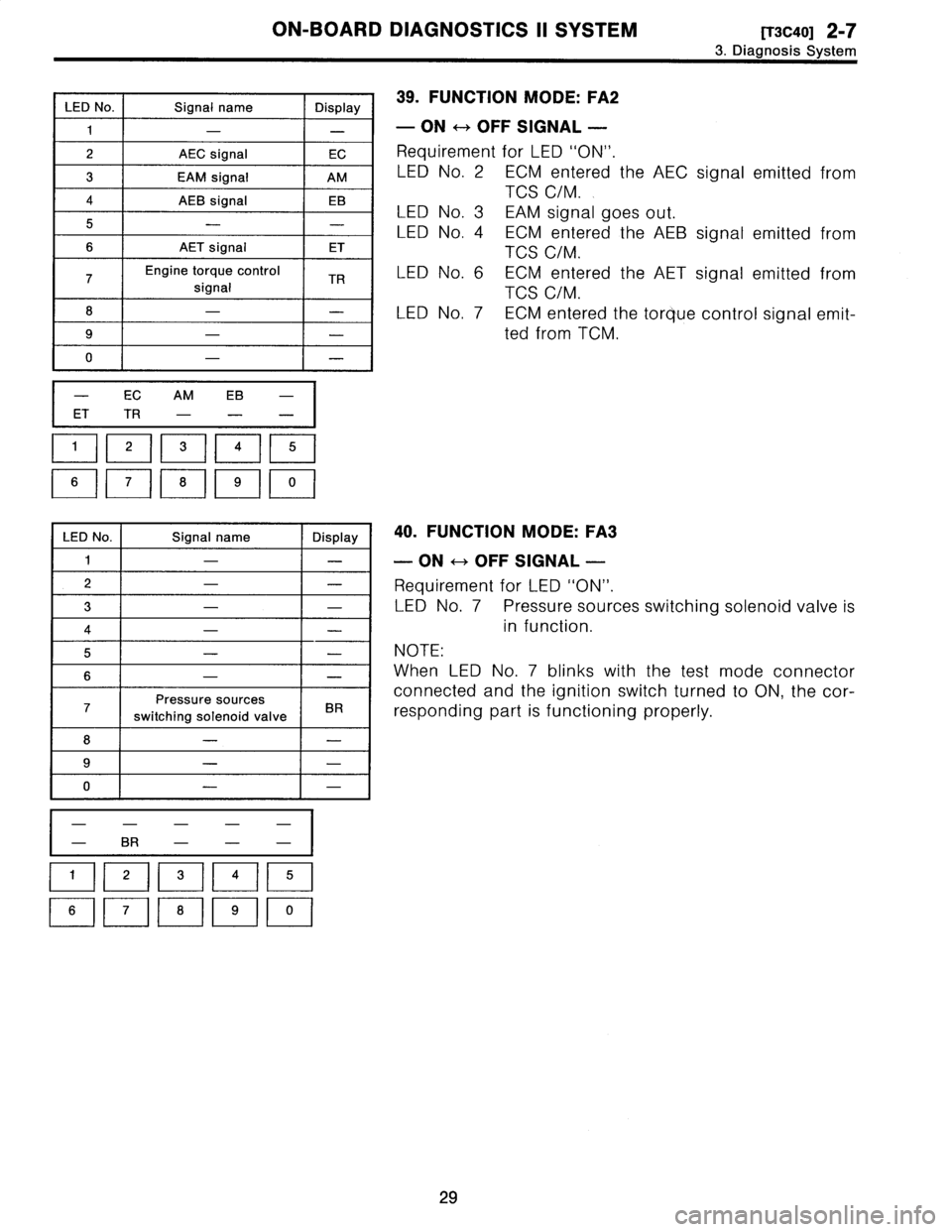
39
.
FUNCTION
MODE
:
FA2
-
ON
H
OFF
SIGNAL
-
Requirement
for
LED
"ON"
.
LED
No
.
2
ECM
entered
the
AEC
signal
emitted
from
TCS
C/M
.
LED
No
.
3
EAM
signal
goes
out
.
LED
No
.
4
ECM
entered
the
AEB
signal
emitted
from
TCS
C/M
.
LED
No
.
6
ECM
entered
the
AET
signal
emitted
from
TCS
C/M
.
LEDNo
.
7
ECM
entered
the
torque
control
signal
emit-
ted
from
TCM
.
40
.
FUNCTION
MODE
:
FA3
-
ON
H
OFF
SIGNAL
-
Requirement
for
LED
"ON"
.
LEDNo
.
7
Pressure
sources
switchingsolenoid
valve
is
in
function
.
NOTE
:
When
LED
No
.
7
blinks
with
the
test
mode
connector
connected
and
the
ignition
switch
turned
to
ON,
the
cor-
responding
part
is
functioning
properly
.
29
Page 59 of 2890
![SUBARU LEGACY 1996 Service Repair Manual
ON-BOARD
DIAGNOSTICS
II
SYSTEM
[TSO1]
2-7
5
.
Specified
Data
C
t
T
il
Signal
(V)
Content
onnec
or
erm
na
Ignition
SW
ON
Note
No
.
No
.
Engine
ON
(Idling)
(Engine
OFF)
Starter
switch
B84
8600
Crank SUBARU LEGACY 1996 Service Repair Manual
ON-BOARD
DIAGNOSTICS
II
SYSTEM
[TSO1]
2-7
5
.
Specified
Data
C
t
T
il
Signal
(V)
Content
onnec
or
erm
na
Ignition
SW
ON
Note
No
.
No
.
Engine
ON
(Idling)
(Engine
OFF)
Starter
switch
B84
8600
Crank](/manual-img/17/57433/w960_57433-58.png)
ON-BOARD
DIAGNOSTICS
II
SYSTEM
[TSO1]
2-7
5
.
Specified
Data
C
t
T
il
Signal
(V)
Content
onnec
or
erm
na
Ignition
SW
ON
Note
No
.
No
.
Engine
ON
(Idling)
(Engine
OFF)
Starter
switch
B84
8600
Cranking
:
8
to
14
A/C
switch
B84
60
ON
:
10
-
13
ON
:
13
-
14
OFF
:
0
OFF
:
0
Ignition
switch
B84
85
10-13
13-
14
-
Neutral
position
switch
B84
82
ON
:
0
Switch
is
ON
when
shift
isin
"
"
OFF
:
5
.0f0
.5
"N
or
"P
position
.
Test
mode
connector
884
84
55
When
connected
:
0
Knock
Signal
B84
32
.8
2
.8
-
sensor
Shield
B84
56
00
-
AT/MT
identification
B84
81
55
When
measuring
voltage
between
ECM
and
body
.
Back-up
power
supply
B84
39
10-1313-14
Ignition
switch
"OFF"
:
10
-
13
Control
unit
power
1
supply
B84
2
10-13
13-14
-
Ignition
#
1,
#
2
B84
41
0
1
-3
.4
-
control
#
3,
#
4
B84
400
1
-3
.4
-
#
1
B84
96
10-13
1-14
Waveform
Fuel
#
2
B84
70
10-13
1-14
Waveform
injector
#
3
B84
44
10-13
1-14
Waveform
#
4
B84
16
10-13
1
-14
Waveform
Idle
air
OPEN
endB84
14
-
1
-13
Waveform
control
solenoid
CLOSE
B84
13
-
13-1
Waveform
valve
end
Fuel
pump
relay
g84
32
ON
:
0
.5,
or
less0
.5,
or
less
-
control
OFF
:
10
-
13
A/C
relay
control
B84
31
ON
:
0
.5,
orless
ON
:
0
.5,
or
less
OFF
:
10
-
13
OFF
:
13
-
14
Radiator
fan
relay
1
ON
:
0
.5,
or
less
ON
:
0
.5,
or
less
control
B84
74
OFF
:
10
-
13
OFF
:
13
-
14
Radiator
fan
relay2
B84
73
ON
:
0
.5,
or
less
ON
:
0
.5,
or
less
With
A/C
vehicles
only
control
OFF
:
10
-
13
OFF
:
13
-
14
Self-shutoff
control
B84
63
10-13
13-14
-
Malfunction
indicator
B84
58Light
"ON"
:
1,
or
less
lamp
Light
"OFF"
:
10
-
14
Engine
speed
output
B84
64
-
0
-
13,
or
moreWaveform
Torque
control
signal
B84
79
5
5
-
Mass
air
flow
signal
B84
47
0-0
.3
0
.8-
1
.2
-
Purge
control
solenoid
B84
72
ON
:
1,
or
less
ON
:
1,
or
less
valve
OFF
:
10
-
13
OFF
:
13
-
14
Atmospheric
pressure
B84
263
.9-4
.1
2
.0-2
.3
-
sensor
Pressure
sources
ON
:
1,
or
less
ON
:
1,
or
less
switching
solenoid
B84
15
OFF
:
10
-
13
OFF
:
13
-
14valve
EGR
solenoid
valve
B84
71
ON
:
1,
or
less
ON
:
1,
or
less
OFF
:
10
-
13
OFF
:
13
-
14
Front
oxygen
sensor
g84
38
0-1
.0
0-1
.0
-
heater
signal
45
Page 86 of 2890

ON-BOARD
DIAGNOSTICS
11
SYSTEM
[T11aoj
2-7
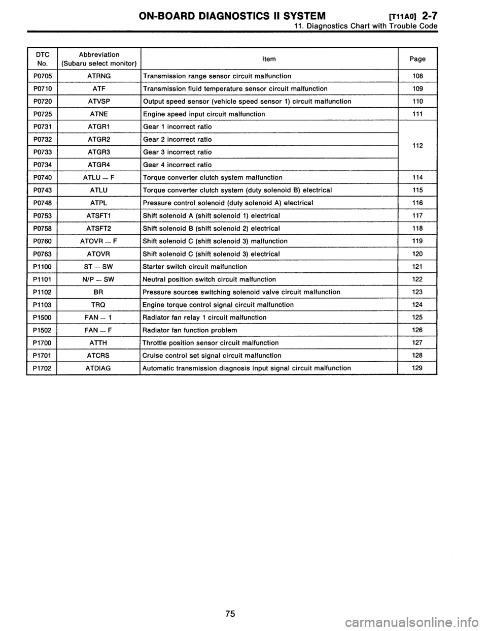
11
.
Diagnostics
Chart
with
Trouble
Code
DTC
No
.
Abbreviation
(Subaru
select
monitor)
Item
Page
P0705
ATRNG
Transmissionrange
sensor
circuit
malfunction
108
P0710
ATF
Transmission
fluid
temperature
sensor
circuit
malfunction
109
P0720
ATVSP
Output
speed
sensor
(vehicle
speed
sensor
1)
circuit
malfunction
110
P0725
ATNE
Engine
speed
input
circuit
malfunction
111
P0731
ATGR1
Gear
1
incorrect
ratio
P0732
ATGR2
Gear
2
incorrect
ratio
1
2
P0733
ATGR3
Gear
3
incorrect
ratio
1
P0734
ATGR4
Gear
4
incorrect
ratio
P0740
ATLU
-
F
Torque
converter
clutch
system
malfunction
114
P0743
ATLU
Torque
converter
clutch
system
(duty
solenoid
B)
electrical
115
P0748
ATPL
Pressure
control
solenoid
(duty
solenoid
A)
electrical
116
P0753
ATSFTi
Shift
solenoid
A
(shift
solenoid
1)
electrical
117
P0758
ATSFT2
Shift
solenoid
B
(shift
solenoid
2)
electrical
118
P0760
ATOVR
-
F
Shift
solenoid
C
(shift
solenoid
3)
malfunction
119
P0763
ATOVR
Shift
solenoid
C
(shift
solenoid
3)
electrical
120
P1100
ST
-
SW
Starter
switch
circuit
malfunction
121
P1101
N/P
-
SW
Neutral
position
switch
circuit
malfunction
122
P1102
BR
Pressure
sources
switching
solenoid
valve
circuit
malfunction
123
P1103
TRQ
Engine
torque
control
signal
circuit
malfunction
124
P1500
FAN
-
1
Radiator
fan
relay
1
circuit
malfunction
125
P1502
FAN
-
F
Radiator
fan
function
problem
126
P1700
ATTH
Throttle
position
sensor
circuit
malfunction
127
P1701
ATCRS
Cruise
control
set
signal
circuit
malfunction
128
P1702
ATDIAG
Automatic
transmission
diagnosis
inputsignal
circuit
malfunction
I
129
75
Page 125 of 2890
2-7
[T11AV0]
ON-BOARD
DIAGNOSTICS
11
SYSTEM
11
.
Diagnostics
Chart
with
Trouble
Code
AV
:
DTC
P0740
-
TORQUE
CONVERTER
CLUTCH
SYSTEM
MALFUNCTION
(ATLU
-
F)
-
WIRING
DIAGRAM
:
Automatic
transmission
Duty
ATF
Vehicle
solenoid
temperature
speed
B
sensor
sensorl
854
Brake
Throttle
b~
B55
1
Ii
t
positions
856
B11
T4
B53
TCM
Inhibitor
switch
N
00
0
a
t
~
3
1
B12
T3
Combination
meter
Speedometer
ECM
circuit
B84
e
:
B54
b
:
855
c
:
B56BI1B53812
O
123456
123456712345678910
81
1
234
5
67
8
9101112
1234
5678
910
11
12
13141516
3132
33
3435
363738394
0
4142
4344
6970
58596061626364L
111
9
1
10
1
11
1
12
1
13
1
14
1
15
11
6
789
101112
1
11
1
12
1
13
1
14
1
15
1
16
1
171819
20
1314
I
I6
1
2349
10
1112
8485
86
87888990
91
E3
1
0
-
4
1
95
96
12
B2M0587
NOTE
:
For
the
diagnostic
procedure
on
torque
converter
clutch
system
malfunction
(DTC
P0740),
referto
2-7
[T10AV0]*2
.
114
Page 126 of 2890
ON-BOARD
DIAGNOSTICS
II
SYSTEM
[r1iawo1
2-7
11
.
Diagnostics
Chart
with
Trouble
Code
AW
:
DTC
P0743
-
TORQUE
CONVERTER
CLUTCH
SYSTEM
(DUTY
SOLENOID
B)
ELECTRICAL
(ATLU)
-
WIRING
DIAGRAM
:
855
-
BII
T4
TCM
855
12345678
1911011121314t
16
B11
131421516
OBD0413
I
NOTE
:
For
the
diagnostic
procedure
on
torque
converter
clutch
system
electrical
(DTC
P0743),
refer
to
2-7
[T10AW0]*2
.
115