Page 2495 of 2890
10M2
CHECK TIRE.
: Are the tire specifications correct?
: Go to next.
: Replace tire.
: Is the tire worn excessively?
: Replace tire.
: Go to next.
: Is the tire pressure correct?
: Go to step10M3.
: Adjust tire pressure.
10M3CHECK ABS SENSOR MECHANICAL
TROUBLE.
: Tightening torque:
32±10 N⋅m (3.3±1.0 kg-m, 24±7 ft-lb)
Are the ABS sensor installation bolts tight-
ened securely?
: Go to next.
: Tighten ABS sensor installation bolts securely.
: Tightening torque:
13±3 N⋅m (1.3±0.3 kg-m, 9±2.2 ft-lb)
Are the ABS sensor installation bolts tight-
ened securely?
: Go to next step.
: Tighten ABS sensor installation bolts securely.
G4M0700
1) Measure tone wheel to pole piece gap over entire
perimeter of the wheel.
: Is the gap within the specifications shown
in the following table?
SpecificationsFront wheel Rear wheel
0.9—1.4 mm
(0.035—0.055 in)0.7—1.2 mm
(0.028—0.047 in)
155
4-4cBRAKES [ABS 5.3 TYPE]
10. Diagnostics Chart with Select Monitor
Page 2580 of 2890
![SUBARU LEGACY 1996 Service Repair Manual B4M0903A
10AE8CHECK BATTERY SHORT AT ABSCM
MONITOR TERMINAL.
1) Disconnect connector cover from ABSCM connector.
<Ref. to 4-4c [T8C1] steps 5) to 8).>
2) Connect all connectors.
3) Turn ignition switc](/manual-img/17/57433/w960_57433-2579.png "SUBARU LEGACY 1996 Service Repair Manual B4M0903A
10AE8CHECK BATTERY SHORT AT ABSCM
MONITOR TERMINAL.
1) Disconnect connector cover from ABSCM connector.
<Ref. to 4-4c [T8C1] steps 5) to 8).>
2) Connect all connectors.
3) Turn ignition switc")
B4M0903A
10AE8CHECK BATTERY SHORT AT ABSCM
MONITOR TERMINAL.
1) Disconnect connector cover from ABSCM connector.
2) Connect all connectors.
3) Turn ignition switch to ON.
4) Measure voltage between ABSCM connector terminals.
: Connector & terminal
(F49) No. 10 (+)—No.1(�)
Is voltage less than 2 V?
: Go to next step.
: Replace ABSCM.
5) Turn ignition switch to OFF.
6) Measure voltage between ABSCM connector terminals.
: Connector & terminals
(F49) No. 10 (+)—No.1(�)
Is voltage less than 2 V?
: Go to step10AE9.
: Replace ABSCM.
B4M0808
10AE9
CHECK MOTOR GROUND.
: Tightening torque:
32±10 N⋅m (3.3±1.0 kg-m, 24±7 ft-lb)
Is the motor ground terminal tightly
clamped?
: Go to step10AE10.
: Tighten the clamp of motor ground terminal.
B4M0904A
10AE10CHECK ABSCM MOTOR DRIVE TERMI-
NAL.
1) Measure voltage between ABSCM connector terminals.
2) Operate the check sequence.
: Connector & terminals
(F49) No. 22 (+)—No.1(�)
Does the voltage drop from 10—13Vto
less than 1.5 V, and rise to 10—13 V again
when carrying out the check sequence?
: Go to step10AE11.
: Replace ABSCM.
240
4-4cBRAKES [ABS 5.3 TYPE]
10. Diagnostics Chart with Select Monitor
Page 2585 of 2890

Is the motor ground terminal tightly
clamped?
: Go to step10AF4.
: Tighten the clamp of motor ground te")
B4M0808
10AF3
CHECK MOTOR GROUND.
: Tightening torque:
32±10 N⋅m (3.3±1.0 kg-m, 24±7 ft-lb)
Is the motor ground terminal tightly
clamped?
: Go to step10AF4.
: Tighten the clamp of motor ground terminal.
B4M0905A
10AF4
CHECK MOTOR OPERATION.
1) Disconnect connector (F49) from ABSCM.
2) Disconnect connector cover from ABSCM connector
(F49).
3) Connect connector (F49) to ABSCM.
4) Connect motor relay to relay box.
5) Connect all connectors.
6) Measure voltage between ABSCM connector terminal.
7) Operate the check sequence.
: Connector & terminals
(F49) No. 10 (+)—No.1(�)
Does the voltage raise from less than 1.5 V
to 10—13 V, and return to less than 1.5 V
again when carrying out the check
sequence?
Can motor revolution noise (buzz) be heard
when carrying out the check sequence?
: Go to step10AF5.
: Replace hydraulic unit.
10AF5CHECK POOR CONTACT IN CONNEC-
TOR BETWEEN HYDRAULIC UNIT,
RELAY BOX AND ABSCM.
: Is there poor contact in connector between
hydraulic unit, relay box and ABSCM?
: Repair connector.
: Go to step10AF6.
245
4-4cBRAKES [ABS 5.3 TYPE]
10. Diagnostics Chart with Select Monitor
Page 2746 of 2890
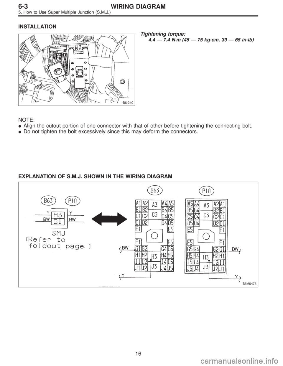
INSTALLATION
B6-240
Tightening torque:
4.4 — 7.4 N⋅m (45 — 75 kg-cm, 39 — 65 in-lb)
NOTE:
�Align the cutout portion of one connector with that of other before tightening the connecting bolt.
�Do not tighten the bolt excessively since this may deform the connectors.
EXPLANATION OF S.M.J. SHOWN IN THE WIRING DIAGRAM
B6M0475
16
6-3WIRING DIAGRAM
5. How to Use Super Multiple Junction (S.M.J.)
Page 2880 of 2890

�In this manual, the following symbols are used.
*: Selective part
�: Replacement part
: Should be lubricated with oil.
: Should be lubricated with grease.
: Sealing point
: Tightening torque
�WARNING, CAUTION, NOTE
�WARNING: Indicates the item which must be observed precisely during performance of maintenance ser-
vices in order to avoid injury to the mechanics and other persons.
�CAUTION: Indicates the item which must be followed precisely during performance of maintenance ser-
vices so as to avoid damage and breakage to the vehicle and its parts and components.
�NOTE: Indicates the hints, knacks, etc. which make the maintenance job easier.
�SPECIAL TOOLS
When any special tool is required to perform the job, it is identified by“ST”in the applicable illustration and its
part number is shown in the manual.
M1H0120
1. Procedures for adjusting backlash
1) Set steering wheel to the straight-ahead position.
2) Remove the exhaust pipe
3) Loosen the lock nut with ST.
�
{ST1 921650000 STEERING GEARBOX WRENCH
ST2 921550000 STEERING GEARBOX WRENCH
Description
(of job method)
Shows the part name
Shows the part number
Tells that two kinds of special tools are required.
When two or more kinds of special tools are required to do
a job, they are identified by ST1, ST2,......respectively.
�
��
5