Page 212 of 2890

~
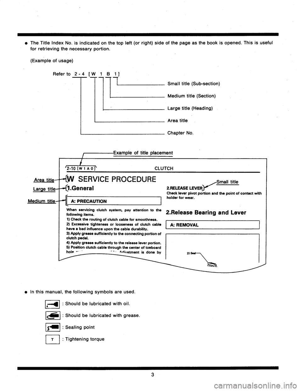
The
Title
Index
No
.
is
indicated
on
thetop
left
(or
right)
side
of
the
page
asthe
book
is
opened
.
This
is
useful
for
retrieving
the
necessary
portion
.
(Example
of
usage)
Refer
to
2
-
4
[
W
1
B
1
7
77
Small
title
(Sub-section)
2-tOfwI
no
Medium
title
(Section)
Large
title
(Heading)
Area
title
Chapter
Na
of
title
placement
CLUTCH
SERVICE
PROCEDURE
Large
title
.General
11
A
:
PRECAUTION
I
When
servicing
clutch
system,
pay
attention
tothe
following
items
.
t)
Check
the
routing
ofclutch
cable
for
smoothness
.
2)
Excessive
tighteness
or
looseness
of
clutch
cable
have
a
bad
influence
upon
the
cable
durability
.
3)
Apply
grease
sufficiently
to
the
connecting
portion
ofclutch
pedal
.
4)
Apply
grease
sufficiently
to
the
release
leverportion
.
5)
Position
clutch
cable
through
the
center
of
toBboard
hole
-
'
`
A
.+anstment
is
done
by
In
this
manual,
thefollowing
symbols
are
used
.
Shouldbe
lubricated
with
oil
.
Shouldbe
lubricated
with
grease
.
Sealing
point
Tightening
torque
Small
title
2
.RELEASE
LEVER
Check
leverpivot
portion
and
the
point
of
contact
with
holder
for
wear
.
2
.Release
Bearing
and
Lever
A
:
REMOVAL
2)
Seal
3
Page 280 of 2890
B2M0313
7) Remove front exhaust pipe and center exhaust pipe
from hanger bracket.
CAUTION:
Be careful not to pull down front exhaust pipe and
center exhaust pipe.
B2M0060
8) Separate front catalytic converter from front exhaust
pipe and center exhaust pipe.
B2M0060
B: INSTALLATION
CAUTION:
Replace gaskets with new ones.
1) Install front catalytic converter to front exhaust pipe and
center exhaust pipe.
Tightening torque:
30±5 N⋅m (3.1±0.5 kg-m, 22.4±3.6 ft-lb)
B2M0313
2) Install front exhaust pipe and center exhaust pipe.
And temporarily tighten bolt which installs center exhaust
pipe to hanger bracket.
B2M0054
3) Tighten bolts which hold front exhaust pipe onto cylin-
der heads.
Tightening torque:
30±5 N⋅m (3.1±0.5 kg-m, 22.4±3.6 ft-lb)
3
2-1SERVICE PROCEDURE
1. Front Catalytic Converter
Page 315 of 2890
2. Cylinder Head and Camshaft
B2M0103A
�1Rocker cover (RH)
�
2Rocker cover gasket
�
3Camshaft support (RH)
�
4O-ring
�
5Camshaft (RH)
�
6Intake valve guide
�
7Exhaust valve guide
�
8Oil seal
�
9Cylinder head (RH)
�
10Cylinder head gasket
�
11Cylinder head (LH)
�
12Plug
�
13Camshaft (LH)
�
14O-ring
�
15Camshaft support (LH)�
16Oil seal
�
17Oil filler cap
�
18Gasket
�
19Oil filler pipe
�
20O-ring
�
21Rocker cover gasket
�
22Rocker cover (LH)
Tightening torque: N⋅m (kg-m, ft-lb)
T1: Refer to 2-3 [W6E1].
T2: 5±1 (0.5±0.1, 3.6±0.7)
T3: 10 (1.0, 7)
T4: 16 (1.6, 12)
7
2-3COMPONENT PARTS
2. Cylinder Head and Camshaft
Page 316 of 2890
3. Cylinder Head and Valve Assembly
B2M0380A
�1Exhaust valve
�
2Intake valve
�
3Intake valve oil seal
�
4Valve spring
�
5Retainer
�
6Retainer key
�
7Exhaust valve oil seal
�
8Rocker shaft support
�
9Rocker shaft support
�
10Rocker shaft support�
11Rocker shaft
�
12Hydraulic lash adjuster
�
13Intake valve rocker arm
�
14Exhaust valve rocker arm
�
15Spring
Tightening torque: N⋅m (kg-m, ft-lb)
T1: 5±1 (0.5±0.1, 3.6±0.7)
T2: 12±1 (1.2±0.1, 8.7±0.7)
8
2-3COMPONENT PARTS
3. Cylinder Head and Valve Assembly
Page 347 of 2890
3. RELATED PARTS
1) Install valve rocker assembly.
B2M0418B
Tightening torque: N⋅m (kg-m, ft-lb)
T1: 5±1 (0.5±0.1, 3.6±0.7)
T2: 12±1 (1.2±0.1, 8.7±0.7)
2) Install timing belt, camshaft sprockets and related parts.
6. Cylinder Head
A: REMOVAL
1. INTAKE MANIFOLD
1) Release fuel pressure.
2) Drain engine coolant.
3) Remove intake manifold.
4) Remove engine coolant pipe.
38
2-3SERVICE PROCEDURE
5. Camshaft - 6. Cylinder Head
Page 348 of 2890
3. RELATED PARTS
1) Install valve rocker assembly.
B2M0418B
Tightening torque: N⋅m (kg-m, ft-lb)
T1: 5±1 (0.5±0.1, 3.6±0.7)
T2: 12±1 (1.2±0.1, 8.7±0.7)
2) Install timing belt, camshaft sprockets and related parts.
6. Cylinder Head
A: REMOVAL
1. INTAKE MANIFOLD
1) Release fuel pressure.
2) Drain engine coolant.
3) Remove intake manifold.
4) Remove engine coolant pipe.
38
2-3SERVICE PROCEDURE
5. Camshaft - 6. Cylinder Head
Page 356 of 2890
D: ASSEMBLY
B2M0121B
Tightening torque: N⋅m (kg-m, ft-lb)
T1: 5±1 (0.5±0.1, 3.6±0.7)
T2: 10 (1.0, 7)
T3: 12±1 (1.2±0.1, 8.7±0.7)
T4: 16 (1.6, 12)
1) Install plug (cylinder head LH) by using ST.
ST 499587100 OIL SEAL INSTALLER
2) Installation of valve spring and valve
(1) Place cylinder head on ST.
ST 498267200 CYLINDER HEAD TABLE
(2) Coat stem of each valve with engine oil and insert
valve into valve guide.
CAUTION:
When inserting valve into valve guide, use special care
not to damage the oil seal lip.
46
2-3SERVICE PROCEDURE
6. Cylinder Head
Page 359 of 2890
(7) Further tighten all bolts by 80 to 90°in numerical
sequence.
CAUTION:
Ensure that the total“re-tightening angle”[steps (6)
and (7) above] do not exceed 180°.
3) Install oil level gauge guide attaching bolt (left side
only).
4) Install timing belt, camshaft sprocket and related parts.
2. INTAKE MANIFOLD
CAUTION:
Use dry compressed air to remove foreign particles
before installing each solenoid valve and sensor.
1) Install engine coolant pipe.
2) Install intake manifold.
3) Remove ENGINE STAND (ST).
49
2-3SERVICE PROCEDURE
6. Cylinder Head