Page 695 of 2890
B2M0313
7) Remove front exhaust pipe and center exhaust pipe
from hanger bracket.
CAUTION:
Be careful not to pull down front exhaust pipe and
center exhaust pipe.
B2M0060
8) Separate front exhaust pipe from front catalytic con-
verter.
B2M0060
B: INSTALLATION
CAUTION:
Replace gaskets with new ones.
1) Install front catalytic converter to front exhaust pipe.
Tightening torque:
30±5 N⋅m (3.1±0.5 kg-m, 22.4±3.6 ft-lb)
B2M0313
2) Install front exhaust pipe and center exhaust pipe.
And temporarily tighten bolt which installs center exhaust
pipe to hanger bracket.
B2M0054
3) Tighten bolts which hold front exhaust pipe onto cylin-
der heads.
Tightening torque:
30±5 N⋅m (3.1±0.5 kg-m, 22.4±3.6 ft-lb)
5
2-9SERVICE PROCEDURE
1. Front Exhaust Pipe and Center Exhaust Pipe
Page 893 of 2890
 Place the spring retainer on the inner race. Install
the spring to the recessed portion of the piston. Then
tighten eight socket head bolts from the rear side of the
transmission case.
Tig")
G3M0402
(3) Place the spring retainer on the inner race. Install
the spring to the recessed portion of the piston. Then
tighten eight socket head bolts from the rear side of the
transmission case.
Tightening torque:
25±2 N⋅m (2.5±0.2 kg-m, 18.1±1.4 ft-lb)
CAUTION:
Be sure to tighten evenly.
G3M0403
8) Install the band servo sub assembly.
9) Press the O.D. servo retainer into position with ST1 and
ST2, and secure with a snap ring.
ST1 498677010 COMPRESSOR
ST2 399703600 PULLER ASSY
CAUTION:
Perform the following operations with the transmis-
sion case set vertically on wooden blocks.
B3H0013A
10) Installation of the low & reverse brake:
(1) Install dish plate, driven plates, drive plates, and a
retaining plate, and secure with a snap ring.
NOTE:
�Pay attention to the orientation of the dish plate.
�Driven plate : 6
Drive plate : 6
�Dish plate : 1
�
1Snap ring
�
2Retaining plate
�
3Transmission case
�
4Lathe cut seal ring
�
5Dish plate
�
6Piston
�
7Bolt
�
8Lathe cut seal ring
�
9Clutch spring retainer
�
10Forward clutch drum
�
11Drive plate
�
12Driven plate
67
3-2SERVICE PROCEDURE
4. Overall Transmission
Page 971 of 2890
G3M0031
5) Lightly tap the head of front propeller shaft with a cop-
per hammer until center bearing is removed.
CAUTION:
Be careful not to damage the thread portion.
D: INSPECTION
NOTE:
Do not disassemble propeller shaft. Check the following
and replace if necessary.
1) Tube surfaces for dents or cracks
2) Splines for deformation or abnormal wear
3) Joints for non-smooth operation or abnormal noise
4) Center bearing for free play, noise or non-smooth
operation
5) Oil seals for abnormal wear or damage
6) Center bearing for breakage
G3M0030
E: ASSEMBLY
1) Install center bearing onto front propeller shaft.
2) Align marks and install companion flange.
G3M0029
3) Tighten stake nut until center bearing is set in position.
CAUTION:
Be sure to install new stake nut.
Tightening torque:
270±25 N⋅m (27.5±2.5 kg-m, 199±18 ft-lb)
NOTE:
Stake the nut after tightening.
12
3-4SERVICE PROCEDURE
1. Propeller Shaft
Page 990 of 2890
G3M0720
9) Press-fit companion flange with ST1 and ST2.
CAUTION:
Be careful not to damage bearing.
ST1 899874100 INSTALLER
ST2 399780104 WEIGHT
G3M1052
10) Install self-locking nut. Then tighten it with ST.
ST 498427200 FLANGE WRENCH
Tightening torque:
181±15 N⋅m (18.5±1.5 kg-m, 134±11 ft-lb)
G3M0069
11) Install crown gear on differential case.
Tightening Torque:
103±10 N⋅m (10.5±1.0 kg-m, 76±7 ft-lb)
NOTE:
Tighten diagonally while tapping the bolt heads.
G3M1041
12) Before installing side bearing, measure the bearing
width by using a dial gauge, ST1 and ST2.
Standard bearing width:
20.00 mm (0.7874 in)
NOTE:
Set the dial gauge needle to zero, using a standard bear-
ing or block of specified height in advance.
ST1 398227700 WEIGHT
ST2 398237700 GAUGE
G3M0091
13) Press side bearing cone onto differential case with
ST1.
ST1 398487700 DRIFT
31
3-4SERVICE PROCEDURE
2. Rear Differential
Page 1012 of 2890
 Loosen the left and right side steering tie-rods lock nuts.
2) Turn the left and right tie rods equal amounts until the
toe-in is at the specification.
Both the left and right t")
G4M0482
�Adjustment
1) Loosen the left and right side steering tie-rods lock nuts.
2) Turn the left and right tie rods equal amounts until the
toe-in is at the specification.
Both the left and right tie-rods are right-hand threaded. To
increase toe-in, turn both tie-rods clockwise equal amounts
(as viewed from the inside of the vehicle).
3) Tighten tie-rod lock nut.
Tightening torque:
83±5 N⋅m (8.5±0.5 kg-m, 61.5±3.6 ft-lb)
CAUTION:
Correct tie-rod boot, if it is twisted.
NOTE:
Check the left and right wheel steering angle is within
specifications.
M4A0059
4. REAR WHEEL TOE-IN (FWD MODEL)
�Inspection
1) Using a toe-in gauge, measure rear wheel toe-in.
Toe-in: 0±3 mm (0±0.12 in)
2) Mark rear sides of left and right tires at height corre-
sponding to center of spindles and measure distance“B”
between marks.
3) Move vehicle forward so that marks line up with front
sides at height corresponding to center of spindles.
4) Measure distance“A”between left and right marks.
Toe-in can then be obtained by the following equation:
B�A = Toe-in
G4M0483
�Adjustment
1) Remove cap from lateral link and loosen self-locking
nut.
CAUTION:
�When loosening or tightening adjusting bolt, hold
the bolt head and loosen self-locking nut.
�Replace self-locking nut with a new one.
2) Using two wrenches, turn adjusting wheel and adjusting
bolt equally in opposite directions so that toe-in is at the
specification.
11
4-1SERVICE PROCEDURE
1. On-car Services
Page 1014 of 2890
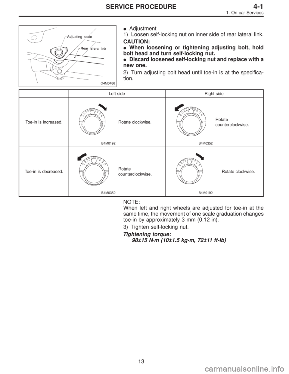
G4M0486
�Adjustment
1) Loosen self-locking nut on inner side of rear lateral link.
CAUTION:
�When loosening or tightening adjusting bolt, hold
bolt head and turn self-locking nut.
�Discard loosened self-locking nut and replace with a
new one.
2) Turn adjusting bolt head until toe-in is at the specifica-
tion.
Left side Right side
Toe-in is increased.
B4M0192
Rotate clockwise.
B4M0352
Rotate
counterclockwise.
Toe-in is decreased.
B4M0352
Rotate
counterclockwise.
B4M0192
Rotate clockwise.
NOTE:
When left and right wheels are adjusted for toe-in at the
same time, the movement of one scale graduation changes
toe-in by approximately 3 mm (0.12 in).
3) Tighten self-locking nut.
Tightening torque:
98±15 N⋅m (10±1.5 kg-m, 72±11 ft-lb)
13
4-1SERVICE PROCEDURE
1. On-car Services
Page 1026 of 2890
 Pull the piston rod fully upward, and install rubber seat
and spring seat.
NOTE:
Ensure that upper spring seat is positioned with“OUT”
mark facing outward.
8) Install strut mount to the")
G4M0511
7) Pull the piston rod fully upward, and install rubber seat
and spring seat.
NOTE:
Ensure that upper spring seat is positioned with“OUT”
mark facing outward.
8) Install strut mount to the piston rod, and tighten the
self-locking nut temporarily.
CAUTION:
Be sure to use a new self-locking nut.
G4M0507
9) Using hexagon wrench to prevent strut rod from turning,
tighten self-locking nut with ST.
Tightening torque:
54±5 N⋅m (5.5±0.5 kg-m, 39.8±3.6 ft-lb)
ST 927760000 STRUT MOUNT SOCKET
10) Loosen the coil spring carefully.
E: INSTALLATION
1) Install strut mount at upper side of strut to body and
tighten with nuts.
Tightening torque:
20±6 N⋅m (2.0±0.6 kg-m, 14.5±4.3 ft-lb)
2) Connect housing to lower side of strut.
3) Position aligning mark on camber adjusting bolt with
aligning mark on lower side bracket of strut.
CAUTION:
�While holding head of adjusting bolt, tighten self-
locking nut.
�Be sure to use new self-locking nut.
Tightening torque:
152±20 N⋅m (15.5±2.0 kg-m, 112±14 ft-lb)
4) Install A.B.S. sensor harness to strut. (A.B.S. equipped
models.)
Tightening torque:
152±20 N⋅m (15.5±2.0 kg-m, 112±14 ft-lb)
5) Install brake hose at lower side of strut with clamp.
G4M0503
6) Install union bolts which secure brake caliper to brake
hose.
Tightening torque:
18±3 N⋅m (1.8±0.3 kg-m, 13.0±2.2 ft-lb)
CAUTION:
Be sure to bleed air from brake system.
7) Install wheels.
NOTE:
Check wheel alignment and adjust if necessary.
25
4-1SERVICE PROCEDURE
4. Front Strut
Page 1062 of 2890
 Install transverse link ball joint to housing.
Tightening torque:
44±6 N⋅m (4.5±0.6 kg-m, 32.5±4.3 ft-lb)
2) While aligning alignment mark on camber adjusting bolt
head, connec")
E: INSTALLATION
1) Install transverse link ball joint to housing.
Tightening torque:
44±6 N⋅m (4.5±0.6 kg-m, 32.5±4.3 ft-lb)
2) While aligning alignment mark on camber adjusting bolt
head, connect housing and strut.
CAUTION:
Use a new self-locking nut.
Tightening torque:
147±15 N⋅m (15±1.5 kg-m, 108±11 ft-lb)
3) Install speed sensor and harness on housing (only
vehicle equipped with A.B.S.).
4) Install disc rotor on hub.
5) Install disc brake caliper on housing.
Tightening torque:
59±10 N⋅m (6±1 kg-m, 43±7 ft-lb)
6) Install front drive shaft.
7) Connect stabilizer link.
G4M0236
8) Install tie-rod end ball joint on housing knuckle arm.
Tightening torque:
27.0±2.5 N⋅m (2.75±0.25 kg-m, 19.9±1.8 ft-lb)
G4M0237
9) While depressing brake pedal, tighten axle nut and lock
it securely.
Tightening torque:
186±20 N⋅m (19±2 kg-m, 137±14 ft-lb)
CAUTION:
�Use a new axle nut.
�Always tighten axle nut before installing wheel on
vehicle. If wheel is installed and comes in contact with
ground when axle nut is loose, wheel bearings may be
damaged.
�Be sure to tighten axle nut to specified torque. Do
not overtighten it as this may damage wheel bearing.
15
4-2SERVICE PROCEDURE
1. Front Axle
 Remove front exhaust pipe and center exhaust pipe
from hanger bracket.
CAUTION:
Be careful not to pull down front exhaust pipe and
center exhaust pipe.
B2M0060
8) Separate front exhaust pip")
 Lightly tap the head of front propeller shaft with a cop-
per hammer until center bearing is removed.
CAUTION:
Be careful not to damage the thread portion.
D: INSPECTION
NOTE:
Do not disass")
 Press-fit companion flange with ST1 and ST2.
CAUTION:
Be careful not to damage bearing.
ST1 899874100 INSTALLER
ST2 399780104 WEIGHT
G3M1052
10) Install self-locking nut. Then tighten it wi")