Page 1130 of 2890
G4M0120
7) Bend lock washer using a chisel.
CAUTION:
Be careful not to scratch rack when bending lock
washer.
G4M0122
8) Rack and pinion backlash adjustment
(1) Loosen adjusting screw.
(2) Rotate input shaft so that rack is in the straight
ahead direction.
(3) Apply grease to sleeve.
�
1Sleeve
�
2Spring
�
3Lock nut
�
4Adjusting screw
G4M0121
(4) Tighten adjusting screw by two threads.
G4M0662
(5) Apply liquid packing to at least 1/3 of entire perim-
eter of adjusting screw thread.
Liquid packing:
THREE BOND 1141
(6) Tighten adjusting screw to 15 N⋅m (1.5 kg-m, 11
ft-lb) and back off 26°.
(7) Install lock nut. While holding adjusting screw with
a wrench, tighten lock nut using ST.
ST 926230000 SPANNER
Tightening torque (Lock nut):
39±10 N⋅m (4.0±1.0 kg-m, 29±7 ft-lb)
NOTE:
�Hold adjusting screw with a wrench to prevent it from
turning while tightening lock nut.
23
4-3SERVICE PROCEDURE
3. Steering Gearbox (Power Steering System) [LHD model]
Page 1134 of 2890
G4M0132
15) After adjusting toe-in and steering angle, tighten lock
nut on tie-rod end.
Tightening torque:
83±5 N⋅m (8.5±0.5 kg-m, 61.5±3.6 ft-lb)
CAUTION:
When adjusting toe-in, hold boot as shown to prevent
it from being rotated or twisted. If twisted, straighten it.
G4M0133
F: ADJUSTMENT
1) Adjust front toe.
Standard of front toe:
IN 3—OUT 3 mm (IN 0.12—OUT 0.12 in)
2) Adjust steering angle of wheels.
Inner wheel: 37.6°±1.5
Outer wheel: 32.6°±1.5
B4M0133A
3) If steering wheel spokes are not horizontal when wheels
are set in the straight ahead position, and error is more
than 5°on the periphery of steering wheel, correctly re-in-
stall the steering wheel.
G4M0135
4) If steering wheel spokes are not horizontal with vehicle
set in the straight ahead position after this adjustment,
correct it by turning the right and left tie-rods in the same
direction by the same turns.
27
4-3SERVICE PROCEDURE
3. Steering Gearbox (Power Steering System) [LHD model]
Page 1143 of 2890

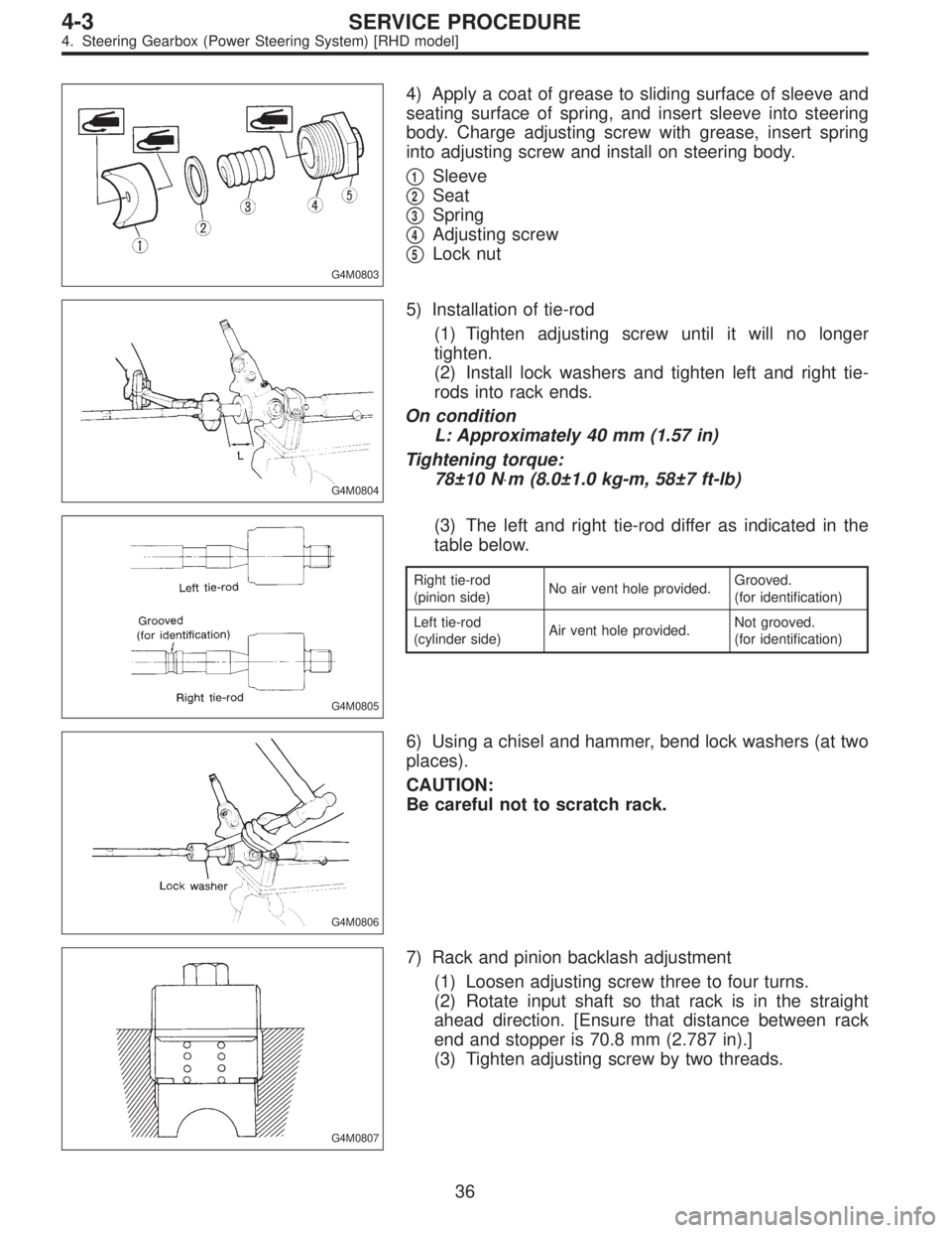
G4M0803
4) Apply a coat of grease to sliding surface of sleeve and
seating surface of spring, and insert sleeve into steering
body. Charge adjusting screw with grease, insert spring
into adjusting screw and install on steering body.
�
1Sleeve
�
2Seat
�
3Spring
�
4Adjusting screw
�
5Lock nut
G4M0804
5) Installation of tie-rod
(1) Tighten adjusting screw until it will no longer
tighten.
(2) Install lock washers and tighten left and right tie-
rods into rack ends.
On condition
L: Approximately 40 mm (1.57 in)
Tightening torque:
78±10 N⋅m (8.0±1.0 kg-m, 58±7 ft-lb)
G4M0805
(3) The left and right tie-rod differ as indicated in the
table below.
Right tie-rod
(pinion side)No air vent hole provided.Grooved.
(for identification)
Left tie-rod
(cylinder side)Air vent hole provided.Not grooved.
(for identification)
G4M0806
6) Using a chisel and hammer, bend lock washers (at two
places).
CAUTION:
Be careful not to scratch rack.
G4M0807
7) Rack and pinion backlash adjustment
(1) Loosen adjusting screw three to four turns.
(2) Rotate input shaft so that rack is in the straight
ahead direction. [Ensure that distance between rack
end and stopper is 70.8 mm (2.787 in).]
(3) Tighten adjusting screw by two threads.
36
4-3SERVICE PROCEDURE
4. Steering Gearbox (Power Steering System) [RHD model]
Page 1545 of 2890
1. Front Seat
G5M0522
�1Headrest free bushing
�
2Headrest lock bushing
�
3Headrest ASSY
�
4Front backrest frame ASSY
�
5Protector
�
6Cover (Bolt) (outer)
�
7Cover (Bolt) (inner)
�
8Inner belt ASSY
�
9Inner slide rail ASSY�
10Connect wire
�
11Outer slide rail ASSY
�
12Front cushion frame ASSY
�
13Cushion ASSY
�
14Reclining lever
�
15Hinge spring cover
�
16Reclining hinge ASSY
�
17Backrest ASSY
�
18Hinge cover�
19Tilt lever cover
�
20Tilt lever ASSY
Tightening torque: N⋅m (kg-m, ft-lb)
T1: 23±5 (2.3±0.5, 16.6±3.6)
T2: 29±7 (3.0±0.7, 21.7±5.1)
T3: 52±10 (5.3±1.0, 38±7)
2
5-3COMPONENT PARTS
1. Front Seat
Page 1636 of 2890

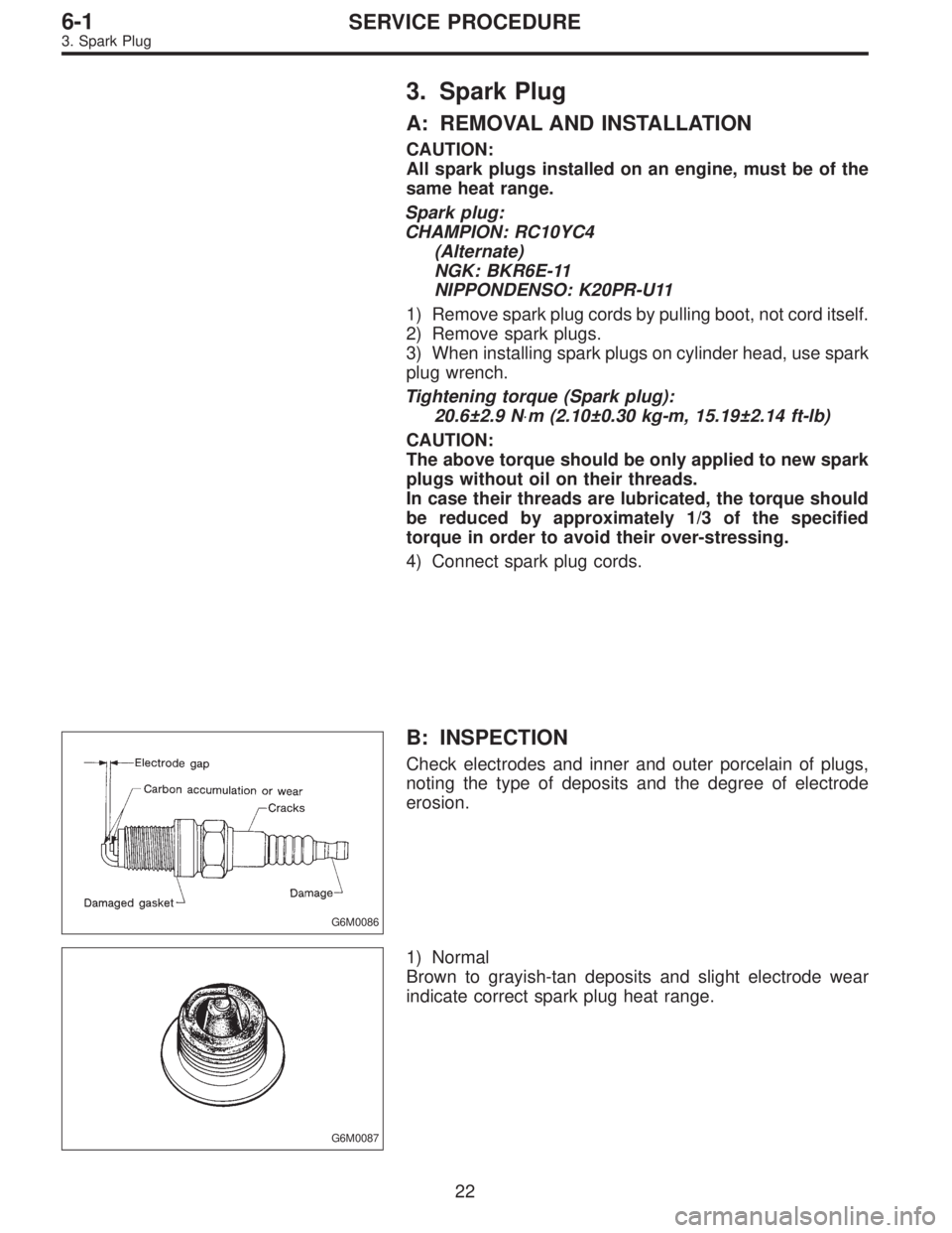
3. Spark Plug
A: REMOVAL AND INSTALLATION
CAUTION:
All spark plugs installed on an engine, must be of the
same heat range.
Spark plug:
CHAMPION: RC10YC4
(Alternate)
NGK: BKR6E-11
NIPPONDENSO: K20PR-U11
1) Remove spark plug cords by pulling boot, not cord itself.
2) Remove spark plugs.
3) When installing spark plugs on cylinder head, use spark
plug wrench.
Tightening torque (Spark plug):
20.6±2.9 N⋅m (2.10±0.30 kg-m, 15.19±2.14 ft-lb)
CAUTION:
The above torque should be only applied to new spark
plugs without oil on their threads.
In case their threads are lubricated, the torque should
be reduced by approximately 1/3 of the specified
torque in order to avoid their over-stressing.
4) Connect spark plug cords.
G6M0086
B: INSPECTION
Check electrodes and inner and outer porcelain of plugs,
noting the type of deposits and the degree of electrode
erosion.
G6M0087
1) Normal
Brown to grayish-tan deposits and slight electrode wear
indicate correct spark plug heat range.
22
6-1SERVICE PROCEDURE
3. Spark Plug
Page 1666 of 2890
2. HEADLIGHT
1) Remove front grille and disconnect connectors from
headlight.
B6M0338
2) Remove bolts which secure headlight and remove
headlight.
Tightening torque:
6.4±0.5 N⋅m (0.65±0.05 kg-m, 4.7±0.4 ft-lb)
NOTE:
When installing the headlight, securely fit clip into locating.
B6M0339
B6M0236
3. COMBINATION SWITCH (WITHOUT AIRBAG
MODEL)
Refer to 5-5 [W7A0] as for removal of combination
switch on airbag equipped model.
1) Remove steering wheel.
2) Remove screws which secure upper column cover to
lower column cover.
3) Remove screws which secure knee protector and
remove knee protector.
CAUTION:
When installing knee protector, ensure that harness is
not caught by adjacent parts.
4) Disconnect connector from body harness and undo
holddown band.
10
6-2SERVICE PROCEDURE
4. Headlight
Page 1687 of 2890
B6M0107A
B: REMOVAL AND INSTALLATION
1. BLADE
Pull out blade following the arrow direction, from arm while
pushing up locking clip.
B6M0112
2. WIPER ARM
1) Remove head cover.
2) Remove nut and wiper arm.
Tightening torque:
5.9±1.5 N⋅m (0.6±0.15 kg-m, 4.3±1.1 ft-lb)
B6M0113
3. WIPER MOTOR
1) Remove cap and special nut.
CAUTION:
Be careful not to strike service tool against nozzle dur-
ing removal.
Tightening torque:
7.4±1.5 N⋅m (0.75±0.15 kg-m, 5.4±1.1 ft-lb)
2) Remove rear gate trim.
3) Undo clips which secure harness, and disconnect con-
nector of wiper motor.
B6M0114
4) Separate washer hoses at joint.
5) Remove attaching screws and take out wiper motor
assembly.
CAUTION:
Be careful not to damage O-ring when removing wiper
motor assembly.
Tightening torque:
5.9±1.5 N⋅m (0.6±0.15 kg-m, 4.3±1.1 ft-lb)
28
6-2SERVICE PROCEDURE
11. Rear Wiper and Washer
Page 2476 of 2890

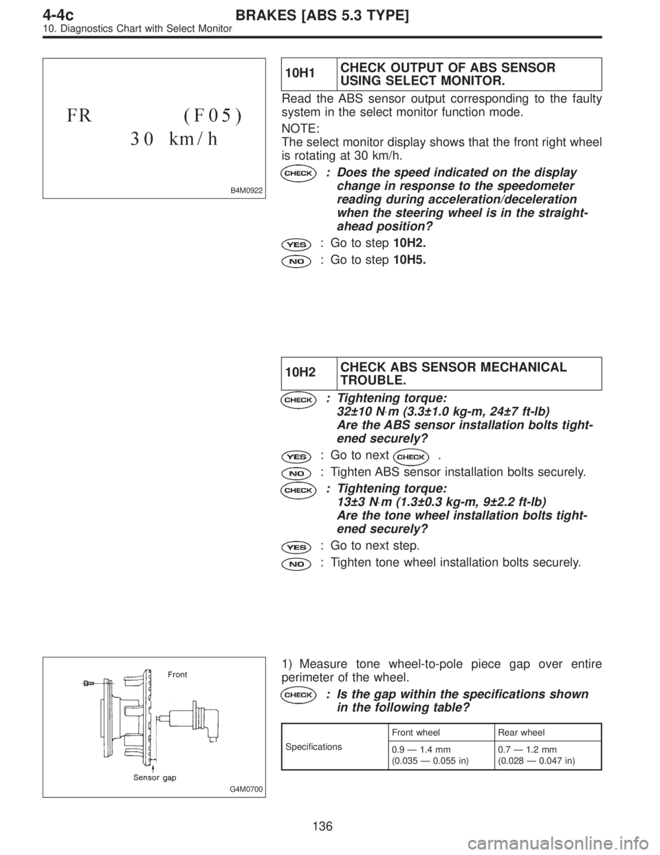
B4M0922
10H1CHECK OUTPUT OF ABS SENSOR
USING SELECT MONITOR.
Read the ABS sensor output corresponding to the faulty
system in the select monitor function mode.
NOTE:
The select monitor display shows that the front right wheel
is rotating at 30 km/h.
: Does the speed indicated on the display
change in response to the speedometer
reading during acceleration/deceleration
when the steering wheel is in the straight-
ahead position?
: Go to step10H2.
: Go to step10H5.
10H2CHECK ABS SENSOR MECHANICAL
TROUBLE.
: Tightening torque:
32±10 N⋅m (3.3±1.0 kg-m, 24±7 ft-lb)
Are the ABS sensor installation bolts tight-
ened securely?
: Go to next.
: Tighten ABS sensor installation bolts securely.
: Tightening torque:
13±3 N⋅m (1.3±0.3 kg-m, 9±2.2 ft-lb)
Are the tone wheel installation bolts tight-
ened securely?
: Go to next step.
: Tighten tone wheel installation bolts securely.
G4M0700
1) Measure tone wheel-to-pole piece gap over entire
perimeter of the wheel.
: Is the gap within the specifications shown
in the following table?
SpecificationsFront wheel Rear wheel
0.9—1.4 mm
(0.035—0.055 in)0.7—1.2 mm
(0.028—0.047 in)
136
4-4cBRAKES [ABS 5.3 TYPE]
10. Diagnostics Chart with Select Monitor