Page 293 of 2890

B2M0955A
B: INSTALLATION
CAUTION:
Leave fuel filler cap open when tightening nuts, to pre-
vent fuel from flowing out through fuel delivery and
return pipes. Close fuel filler cap after tightening nuts.
Installation is in the reverse order of removal. Do the fol-
lowing:
(1) Always use new gaskets.
(2) Ensure sealing portion is free from fuel or foreign
particles before installation.
(3) Tighten nuts in numerical sequence shown in Fig-
ure to specified torque.
Tightening torque:
4.4±1.5 N⋅m (0.45±0.15 kg-m, 3.3±1.1 ft-lb)
G6M0095
9. Fuel Tank Pressure Sensor (2200 cc
AWD Model)
A: REMOVAL AND INSTALLATION
1) Disconnect battery ground cable.
H2M1122B
2) Remove trims.
�4 door model:
Remove right trunk side trim.
B2M0927A
�Wagon model:
(1) Remove right rear quarter upper rear trim.
(2) Remove right strut cap.
(3) Remove right rear quarter pillar lower trim.
11
2-1SERVICE PROCEDURE
8. Fuel Temperature Sensor (2200 cc AWD Model) - 9. Fuel Tank Pressure Sensor (2200 cc AWD Model)
Page 294 of 2890

B2M0955A
B: INSTALLATION
CAUTION:
Leave fuel filler cap open when tightening nuts, to pre-
vent fuel from flowing out through fuel delivery and
return pipes. Close fuel filler cap after tightening nuts.
Installation is in the reverse order of removal. Do the fol-
lowing:
(1) Always use new gaskets.
(2) Ensure sealing portion is free from fuel or foreign
particles before installation.
(3) Tighten nuts in numerical sequence shown in Fig-
ure to specified torque.
Tightening torque:
4.4±1.5 N⋅m (0.45±0.15 kg-m, 3.3±1.1 ft-lb)
G6M0095
9. Fuel Tank Pressure Sensor (2200 cc
AWD Model)
A: REMOVAL AND INSTALLATION
1) Disconnect battery ground cable.
H2M1122B
2) Remove trims.
�4 door model:
Remove right trunk side trim.
B2M0927A
�Wagon model:
(1) Remove right rear quarter upper rear trim.
(2) Remove right strut cap.
(3) Remove right rear quarter pillar lower trim.
11
2-1SERVICE PROCEDURE
8. Fuel Temperature Sensor (2200 cc AWD Model) - 9. Fuel Tank Pressure Sensor (2200 cc AWD Model)
Page 842 of 2890
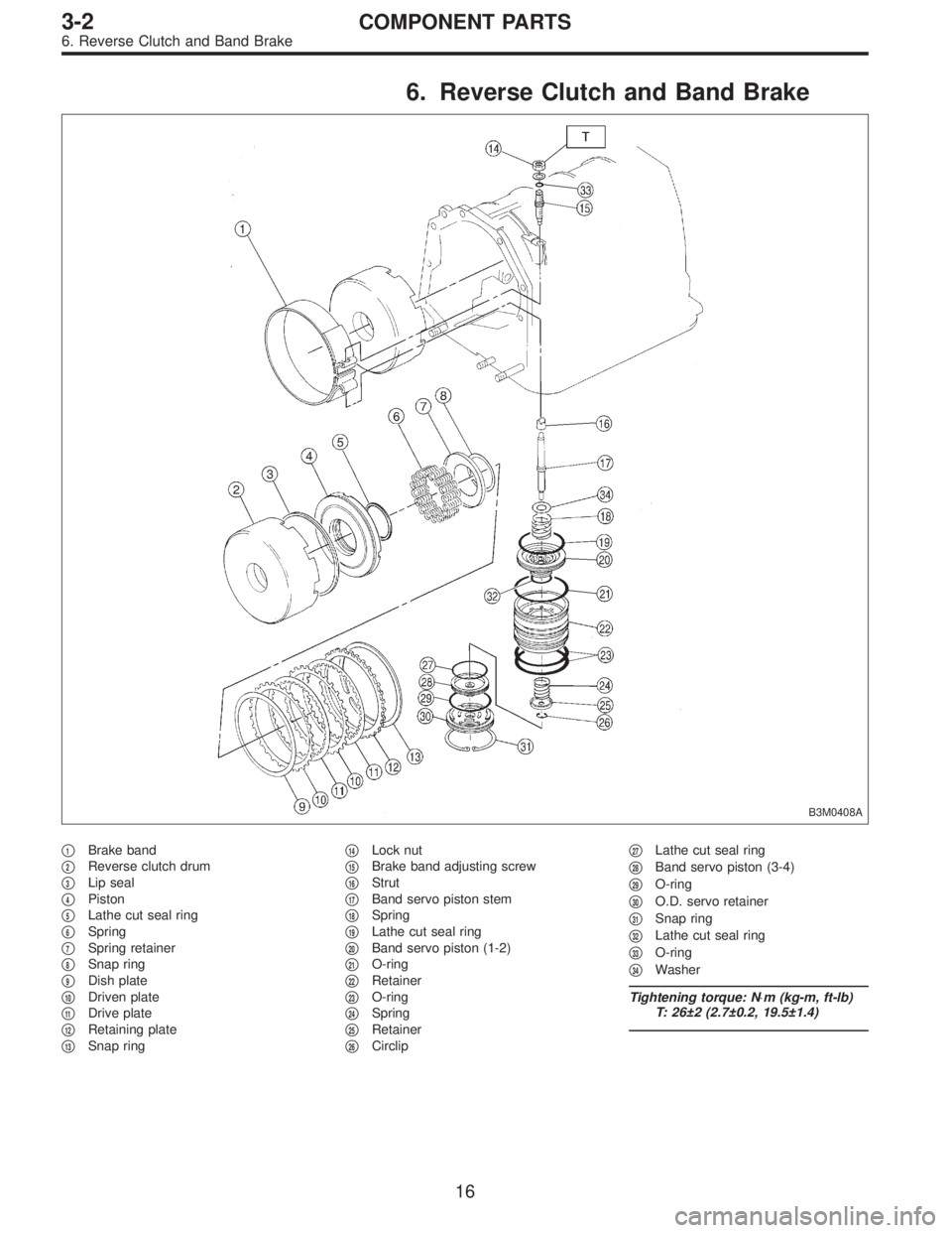
6. Reverse Clutch and Band Brake
B3M0408A
�1Brake band
�
2Reverse clutch drum
�
3Lip seal
�
4Piston
�
5Lathe cut seal ring
�
6Spring
�
7Spring retainer
�
8Snap ring
�
9Dish plate
�
10Driven plate
�
11Drive plate
�
12Retaining plate
�
13Snap ring�
14Lock nut
�
15Brake band adjusting screw
�
16Strut
�
17Band servo piston stem
�
18Spring
�
19Lathe cut seal ring
�
20Band servo piston (1-2)
�
21O-ring
�
22Retainer
�
23O-ring
�
24Spring
�
25Retainer
�
26Circlip�
27Lathe cut seal ring
�
28Band servo piston (3-4)
�
29O-ring
�
30O.D. servo retainer
�
31Snap ring
�
32Lathe cut seal ring
�
33O-ring
�
34Washer
Tightening torque: N⋅m (kg-m, ft-lb)
T: 26±2 (2.7±0.2, 19.5±1.4)
16
3-2COMPONENT PARTS
6. Reverse Clutch and Band Brake
Page 853 of 2890
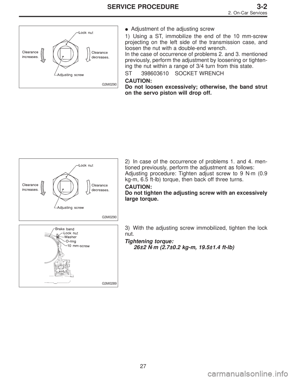
G3M0290
�Adjustment of the adjusting screw
1) Using a ST, immobilize the end of the 10 mm-screw
projecting on the left side of the transmission case, and
loosen the nut with a double-end wrench.
In the case of occurrence of problems 2. and 3. mentioned
previously, perform the adjustment by loosening or tighten-
ing the nut within a range of 3/4 turn from this state.
ST 398603610 SOCKET WRENCH
CAUTION:
Do not loosen excessively; otherwise, the band strut
on the servo piston will drop off.
G3M0290
2) In case of the occurrence of problems 1. and 4. men-
tioned previously, perform the adjustment as follows:
Adjusting procedure: Tighten adjust screw to 9 N⋅m (0.9
kg-m, 6.5 ft-lb) torque, then back off three turns.
CAUTION:
Do not tighten the adjusting screw with an excessively
large torque.
G3M0289
3) With the adjusting screw immobilized, tighten the lock
nut.
Tightening torque:
26±2 N⋅m (2.7±0.2 kg-m, 19.5±1.4 ft-lb)
27
3-2SERVICE PROCEDURE
2. On-Car Services
Page 879 of 2890
G3M0346
11) Remove the three accumulator springs.
G3M0347
12) Loosen the reverse clutch drum lightly by turning the
adjusting screw. Then remove the oil pump housing.
CAUTION:
Be careful not to lose the total end play adjusting
thrust washer.
G3M0348
13) Loosen the brake band adjusting screw with ST, and
take out the strut.
ST 398603610 SOCKET WRENCH
G3M0349
14) Remove the brake band and reverse clutch.
NOTE:
Contract the brake band with a clip.
G3M0350
15) Take out the high clutch.
CAUTION:
Thrust needle bearing and bearing race are removed
together with high clutch. Be careful not to lose them.
53
3-2SERVICE PROCEDURE
4. Overall Transmission
Page 897 of 2890
G3M0418
22) Install the brake band.
CAUTION:
Be careful not to damage the brake band when install-
ing.
NOTE:
Install the strut to the band servo piston stem. Then tighten
it temporarily to avoid tilting the band.
23) Adjustment of total end play and reverse clutch end
play
(1) Measure the distance from the transmission case
mating surface to the recessed portion of the high
clutch drum“L”, and the distance to the top surface of
the reverse clutch drum“M”.
G3M0419
71
3-2SERVICE PROCEDURE
4. Overall Transmission
Page 1005 of 2890

�6Rear bushing
�7Stop rubber (Front)
�8Ball joint
�9Transverse link
�10")
1. Conventional Suspension
1. FRONT SUSPENSION
B4M0765A
�1Front crossmember
�
2Bolt ASSY
�3Housing
�4Washer
�5Stop rubber (Rear)
�6Rear bushing
�7Stop rubber (Front)
�8Ball joint
�9Transverse link
�10Cotter pin
�11Front bushing
�12Stabilizer link
�13Clamp
�14Bushing (2200 cc model)
�15Stabilizer (2200 cc model)
�16Jack-up plate
�17Dust seal
�18Strut mount
�
19Spacer
�20Upper spring seat�
21Rubber seat
�22Dust cover
�23Helper
�24Coil spring
�25Damper strut
�26Adjusting bolt
�27Castle nut
�28Self-locking nut
�29Adapter front crossmember
(OUTBACK model)
�
30Clip (OUTBACK model)
�31Bushing
(2500 cc and OUTBACK model)
�
32Clamp
(2500 cc and OUTBACK model)
Tightening torque: N⋅m (kg-m, ft-lb)
T1: 18±5 (1.8±0.5, 13.0±3.6)
T2: 20±6 (2.0±0.6, 14.5±4.3)
T3: 25±4 (2.5±0.4, 18.1±2.9)
T4: 29±5 (3.0±0.5, 21.7±3.6)
T5: 39 (4, 29)
T6: 44±6 (4.5±0.6, 32.5±4.3)
T7: 49±10 (5.0±1.0, 36±7)
T8: 54±5 (5.5±0.5, 39.8±3.6)
T9: 98±15 (10.0±1.5, 72±11)
T10:152±20 (15.5±2.0, 112±14)
T11:186±10 (19.0±1.0, 137±7)
T12:245±49 (25.0±5.0, 181±36)
4
4-1COMPONENT PARTS
1. Conventional Suspension
Page 1006 of 2890

B4M0766A
�1Stabilizer
�
2Stabilizer bracket
�
3Stabilizer bushing
�
4Clamp
�
5Floating bushing
�
6Stopper
�
7Stabilizer link
�
8Rear lateral link
�
9Bushing (C)
�
10Bush")
2. REAR SUSPENSION (AWD MODEL)
B4M0766A
�1Stabilizer
�
2Stabilizer bracket
�
3Stabilizer bushing
�
4Clamp
�
5Floating bushing
�
6Stopper
�
7Stabilizer link
�
8Rear lateral link
�
9Bushing (C)
�
10Bushing (A)
�
11Front lateral link
�
12Bushing (B)
�
13Trailing link rear bushing
�
14Trailing link
�
15Trailing link front bushing�
16Trailing link bracket
�
17Cap (Protection)
�
18Washer
�
19Rear crossmember
�
20Strut mount cap
�
21Strut mount
�
22Rubber seat upper
�
23Dust cover
�
24Coil spring
�
25Helper
�
26Rubber seat lower
�
27Damper strut
�
28Self-locking nut
�
29Crossmember reinforcement
lower (Sedan model)
�
30Adapter rear crossmember
(OUTBACK model)
Tightening torque: N⋅m (kg-m, ft-lb)
T1: 20±6 (2.0±0.6, 14.5±4.3)
T2: 25±7 (2.5±0.7, 18.1±5.1)
T3: 44±6 (4.5±0.6, 32.5±4.3)
T4: 59±10 (6.0±1.0, 43±7)
T5: 98±15 (10.0±1.5, 72±11)
T6: 98±20 (10.0±2.0, 72±14)
T7: 113±15 (11.5±1.5, 83±11)
T8: 127±20 (13.0±2.0, 94±14)
T9: 137±20 (14.0±2.0, 101±14)
T10:196
+39
�10(20.0+4.0
�1.0, 145+29
�7)
5
4-1COMPONENT PARTS
1. Conventional Suspension
 Remove the three accumulator springs.
G3M0347
12) Loosen the reverse clutch drum lightly by turning the
adjusting screw. Then remove the oil pump housing.
CAUTION:
Be careful not to lose t")
 Install the brake band.
CAUTION:
Be careful not to damage the brake band when install-
ing.
NOTE:
Install the strut to the band servo piston stem. Then tighten
it temporarily to avoid tilt")