Page 1007 of 2890
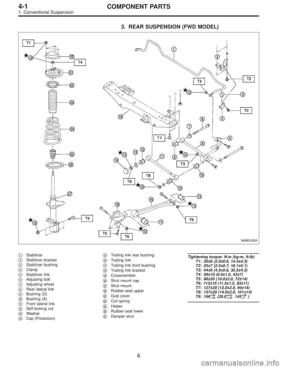
3. REAR SUSPENSION (FWD MODEL)
B4M0185A
�1Stabilizer
�
2Stabilizer bracket
�
3Stabilizer bushing
�
4Clamp
�
5Stabilizer link
�
6Adjusting bolt
�
7Adjusting wheel
�
8Rear lateral link
�
9Bushing (D)
�
10Bushing (A)
�
11Front lateral link
�
12Self-locking nut
�
13Washer
�
14Cap (Protection)�
15Trailing link rear bushing
�
16Trailing link
�
17Trailing link front bushing
�
18Trailing link bracket
�
19Crossmember
�
20Strut mount cap
�
21Strut mount
�
22Rubber seat upper
�
23Dust cover
�
24Coil spring
�
25Helper
�
26Rubber seat lower
�
27Damper strut
Tightening torque: N⋅m (kg-m, ft-lb)
T1: 20±6 (2.0±0.6, 14.5±4.3)
T2: 25±7 (2.5±0.7, 18.1±5.1)
T3: 44±6 (4.5±0.6, 32.5±4.3)
T4: 59±10 (6.0±1.0, 43±7)
T5: 98±20 (10.0±2.0, 72±14)
T6: 113±15 (11.5±1.5, 83±11)
T7: 127±20 (13.0±2.0, 94±14)
T8: 137±20 (14.0±2.0, 101±14)
T9: 196
+39
�10(20.0+4.0
�1.0, 145+29
�7)
6
4-1COMPONENT PARTS
1. Conventional Suspension
Page 1010 of 2890
B4M0567A
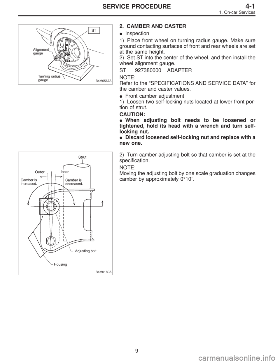
2. CAMBER AND CASTER
�Inspection
1) Place front wheel on turning radius gauge. Make sure
ground contacting surfaces of front and rear wheels are set
at the same height.
2) Set ST into the center of the wheel, and then install the
wheel alignment gauge.
ST 927380000 ADAPTER
NOTE:
Refer to the“SPECIFICATIONS AND SERVICE DATA”for
the camber and caster values.
�Front camber adjustment
1) Loosen two self-locking nuts located at lower front por-
tion of strut.
CAUTION:
�When adjusting bolt needs to be loosened or
tightened, hold its head with a wrench and turn self-
locking nut.
�Discard loosened self-locking nut and replace with a
new one.
B4M0189A
2) Turn camber adjusting bolt so that camber is set at the
specification.
NOTE:
Moving the adjusting bolt by one scale graduation changes
camber by approximately 0°10′.
9
4-1SERVICE PROCEDURE
1. On-car Services
Page 1022 of 2890
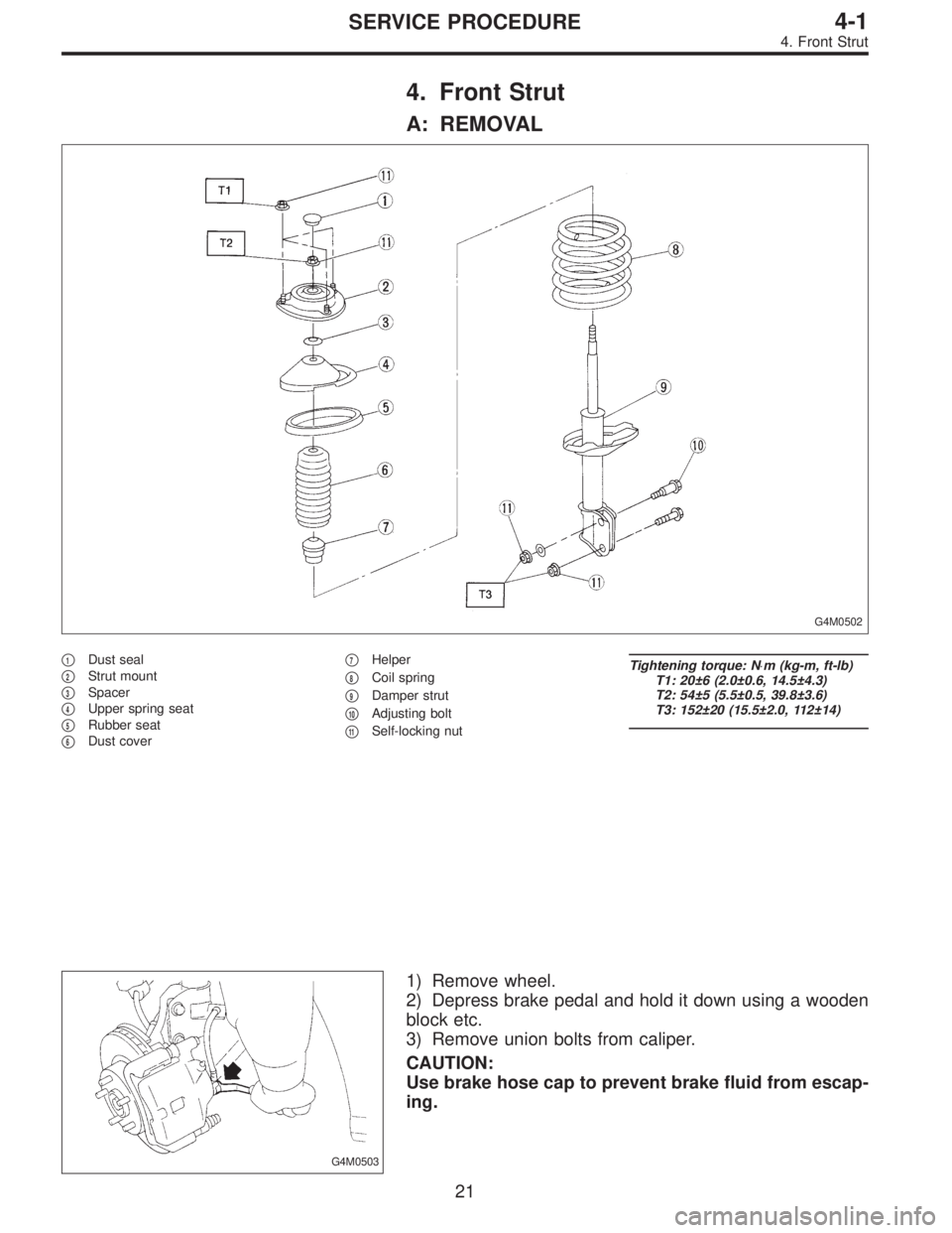
4. Front Strut
A: REMOVAL
G4M0502
�1Dust seal
�
2Strut mount
�
3Spacer
�
4Upper spring seat
�
5Rubber seat
�
6Dust cover�
7Helper
�
8Coil spring
�
9Damper strut
�
10Adjusting bolt
�
11Self-locking nut
Tightening torque: N⋅m (kg-m, ft-lb)
T1: 20±6 (2.0±0.6, 14.5±4.3)
T2: 54±5 (5.5±0.5, 39.8±3.6)
T3: 152±20 (15.5±2.0, 112±14)
G4M0503
1) Remove wheel.
2) Depress brake pedal and hold it down using a wooden
block etc.
3) Remove union bolts from caliper.
CAUTION:
Use brake hose cap to prevent brake fluid from escap-
ing.
21
4-1SERVICE PROCEDURE
4. Front Strut
Page 1023 of 2890
G4M0504
4) Remove brake hose clamp and disconnect brake hose
from strut. Attach brake hose to body using gum tape.
5) Scribe an alignment mark on the camber adjusting bolt
which secures strut to housing.
6) Remove bolt securing the A.B.S. sensor harness.
(A.B.S. equipped models.)
G4M0505
7) Remove two bolts securing housing to strut.
CAUTION:
While holding head of adjusting bolt, loosen self-lock-
ing nut.
8) Remove the three nuts securing strut mount to body.
G4M0506
B: DISASSEMBLY
1) Using a coil spring compressor, compress coil spring.
G4M0507
2) Using ST, remove self-locking nut.
ST 927760000 STRUT MOUNT SOCKET
3) Remove strut mount, upper spring seat and rubber seat
from strut.
4) Gradually decreasing compression force of spring
compressor, and remove coil spring.
5) Remove dust cover and helper.
22
4-1SERVICE PROCEDURE
4. Front Strut
Page 1024 of 2890
 Check for oil leakage.
2) Move the piston rod up and down to")
C: INSPECTION
Check the disassembled parts for cracks, damage and
wear, and replace with new parts if defective.
G4M0508
1. DAMPER STRUT
1) Check for oil leakage.
2) Move the piston rod up and down to check its operates
smoothly without any binding.
3) Play of piston rod
Measure the play as follows:
Fix outer shell and fully extend the rod. Set a dial gauge at
the end of the rod: L [10 mm (0.39 in)], then apply a force
of W [20 N (2 kg, 4 lb)] to threaded portion. With the force
of 20 N (2 kg, 4 lb) applied, read dial gauge indication: P
1.
Apply a force of 20 N (2 kg, 4 lb) in the opposite direction
of“W”, then read dial gauge indication: P
2. The free play
is determined by the following equation:
Play = P
1,P2
Limit of play:
Less than 0.8 mm (0.031 in)
If the play is greater, replace the strut with new one.
2. STRUT MOUNT
Check rubber part for wear, cracks and deterioration, and
replace it with new one if defective.
3. DUST COVER
If any cracks or damage are found, replace it with new one.
4. COIL SPRING
When vehicle posture is uneven, although there are no
considerable reasons like tire puncture, uneven loading,
etc., check coil spring and spring seats for cracks,
deformation, etc., and replace it with a new one if defective.
5. HELPER
Replace it with new one if cracked or damaged.
23
4-1SERVICE PROCEDURE
4. Front Strut
Page 1025 of 2890
 Before installing coil spring, strut mount, etc., on the
strut, check for the presence of air in the dampening force
generating mechanism of the strut since air prevents
proper dampenin")
D: ASSEMBLY
1) Before installing coil spring, strut mount, etc., on the
strut, check for the presence of air in the dampening force
generating mechanism of the strut since air prevents
proper dampening force from being produced.
2) Checking for the presence of air
(1) Place the strut vertically with the piston rod facing
upward.
(2) Move the piston rod to the center of its entire
stroke.
(3) While holding the piston rod end with finger-tips,
move the rod up and down.
(4) If the piston rod moves at least 10 mm (0.39 in) in
step (3), purge air from the strut.
3) Air purging procedure
(1) Place the strut vertically with the piston rod facing
upward.
(2) Fully extend the piston rod.
(3) With the piston rod fully extended, place the piston
rod side down. The strut must stand vertically.
(4) Fully contract the piston rod.
(5) Repeat 3 or 4 times steps (1) through (4) above.
NOTE:
After completely purging air from the strut, be sure to place
the strut with the piston rod facing upward. If it is laid down,
check for entry of air in the strut as outlined under item 2)
above.
B4M0568A
4) Using a coil spring compressor, compress the coil
spring.
NOTE:
Make sure that the vertical installing direction of coil spring
is as shown in figure.
G4M0510
5) Set the coil spring correctly so that its end face fits well
into the spring seat as shown.
6) Install helper and dust cover to the piston rod.
24
4-1SERVICE PROCEDURE
4. Front Strut
Page 1026 of 2890
 Pull the piston rod fully upward, and install rubber seat
and spring seat.
NOTE:
Ensure that upper spring seat is positioned with“OUT”
mark facing outward.
8) Install strut mount to the")
G4M0511
7) Pull the piston rod fully upward, and install rubber seat
and spring seat.
NOTE:
Ensure that upper spring seat is positioned with“OUT”
mark facing outward.
8) Install strut mount to the piston rod, and tighten the
self-locking nut temporarily.
CAUTION:
Be sure to use a new self-locking nut.
G4M0507
9) Using hexagon wrench to prevent strut rod from turning,
tighten self-locking nut with ST.
Tightening torque:
54±5 N⋅m (5.5±0.5 kg-m, 39.8±3.6 ft-lb)
ST 927760000 STRUT MOUNT SOCKET
10) Loosen the coil spring carefully.
E: INSTALLATION
1) Install strut mount at upper side of strut to body and
tighten with nuts.
Tightening torque:
20±6 N⋅m (2.0±0.6 kg-m, 14.5±4.3 ft-lb)
2) Connect housing to lower side of strut.
3) Position aligning mark on camber adjusting bolt with
aligning mark on lower side bracket of strut.
CAUTION:
�While holding head of adjusting bolt, tighten self-
locking nut.
�Be sure to use new self-locking nut.
Tightening torque:
152±20 N⋅m (15.5±2.0 kg-m, 112±14 ft-lb)
4) Install A.B.S. sensor harness to strut. (A.B.S. equipped
models.)
Tightening torque:
152±20 N⋅m (15.5±2.0 kg-m, 112±14 ft-lb)
5) Install brake hose at lower side of strut with clamp.
G4M0503
6) Install union bolts which secure brake caliper to brake
hose.
Tightening torque:
18±3 N⋅m (1.8±0.3 kg-m, 13.0±2.2 ft-lb)
CAUTION:
Be sure to bleed air from brake system.
7) Install wheels.
NOTE:
Check wheel alignment and adjust if necessary.
25
4-1SERVICE PROCEDURE
4. Front Strut
Page 1041 of 2890
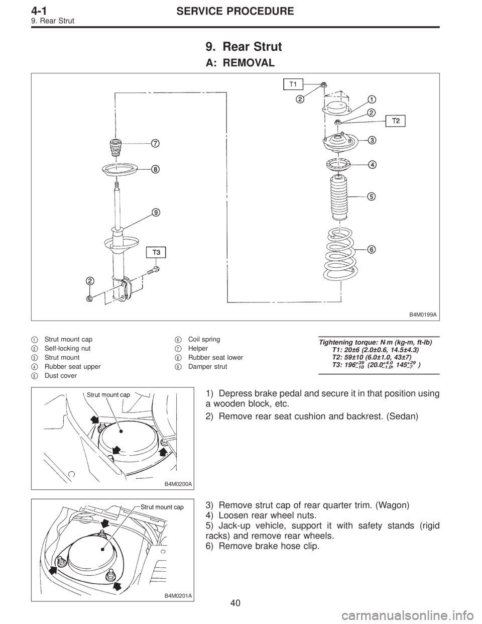
9. Rear Strut
A: REMOVAL
B4M0199A
�1Strut mount cap
�
2Self-locking nut
�
3Strut mount
�
4Rubber seat upper
�
5Dust cover�
6Coil spring
�
7Helper
�
8Rubber seat lower
�
9Damper strut
Tightening torque: N⋅m (kg-m, ft-lb)
T1: 20±6 (2.0±0.6, 14.5±4.3)
T2: 59±10 (6.0±1.0, 43±7)
T3: 196
+39
�10(20.0+4.0
�1.0, 145+29
�7)
B4M0200A
1) Depress brake pedal and secure it in that position using
a wooden block, etc.
2) Remove rear seat cushion and backrest. (Sedan)
B4M0201A
3) Remove strut cap of rear quarter trim. (Wagon)
4) Loosen rear wheel nuts.
5) Jack-up vehicle, support it with safety stands (rigid
racks) and remove rear wheels.
6) Remove brake hose clip.
40
4-1SERVICE PROCEDURE
9. Rear Strut
 Remove brake hose clamp and disconnect brake hose
from strut. Attach brake hose to body using gum tape.
5) Scribe an alignment mark on the camber adjusting bolt
which secures strut to housi")