Page 395 of 2890

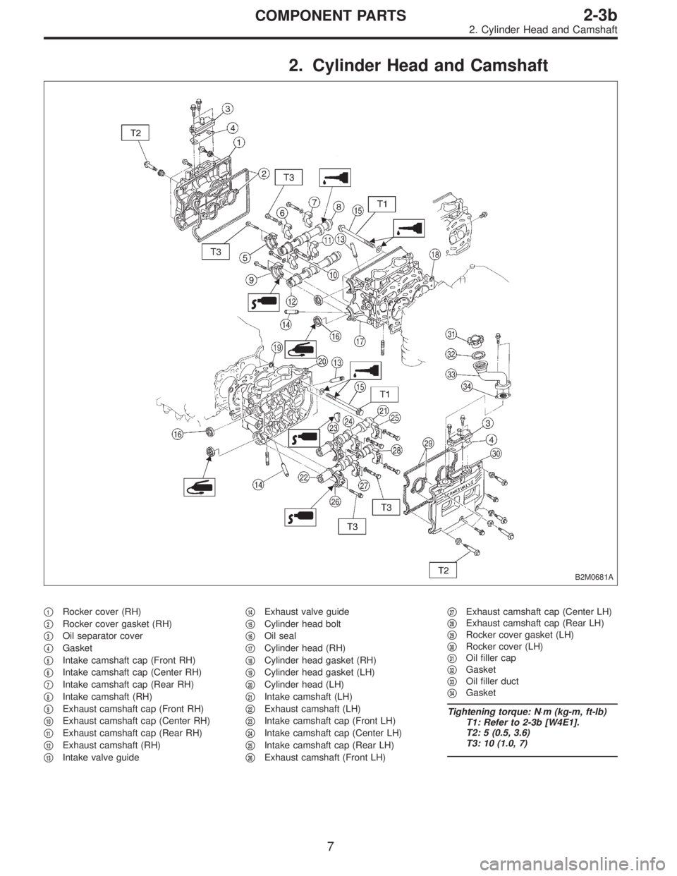
2. Cylinder Head and Camshaft
B2M0681A
�1Rocker cover (RH)
�
2Rocker cover gasket (RH)
�
3Oil separator cover
�
4Gasket
�
5Intake camshaft cap (Front RH)
�
6Intake camshaft cap (Center RH)
�
7Intake camshaft cap (Rear RH)
�
8Intake camshaft (RH)
�
9Exhaust camshaft cap (Front RH)
�
10Exhaust camshaft cap (Center RH)
�
11Exhaust camshaft cap (Rear RH)
�
12Exhaust camshaft (RH)
�
13Intake valve guide�
14Exhaust valve guide
�
15Cylinder head bolt
�
16Oil seal
�
17Cylinder head (RH)
�
18Cylinder head gasket (RH)
�
19Cylinder head gasket (LH)
�
20Cylinder head (LH)
�
21Intake camshaft (LH)
�
22Exhaust camshaft (LH)
�
23Intake camshaft cap (Front LH)
�
24Intake camshaft cap (Center LH)
�
25Intake camshaft cap (Rear LH)
�
26Exhaust camshaft (Front LH)�
27Exhaust camshaft cap (Center LH)
�
28Exhaust camshaft cap (Rear LH)
�
29Rocker cover gasket (LH)
�
30Rocker cover (LH)
�
31Oil filler cap
�
32Gasket
�
33Oil filler duct
�
34Gasket
Tightening torque: N⋅m (kg-m, ft-lb)
T1: Refer to 2-3b [W4E1].
T2: 5 (0.5, 3.6)
T3: 10 (1.0, 7)
7
2-3bCOMPONENT PARTS
2. Cylinder Head and Camshaft
Page 396 of 2890
3. Cylinder Head and Valve Assembly
G2M0706
�1Exhaust valve
�
2Intake valve
�
3Cylinder head
�
4Valve spring seat
�
5Intake valve oil seal
�
6Valve spring
�
7Retainer
�
8Retainer key�
9Hydraulic lash adjuster
�
10Exhaust valve oil seal
Tightening torque: N⋅m (kg-m, ft-lb)
T1: 5 (0.5, 3.6)
T2: 12 (1.2, 9)
8
2-3bCOMPONENT PARTS
3. Cylinder Head and Valve Assembly
Page 420 of 2890
G2M0138
5) Check cam face condition; remove minor faults by
grinding with oil stone. Measure the cam height H; replace
if the limit has been exceeded.
Standard:
Intake 41.68—41.78 mm (1.6409—1.6449 in)
Exhaust 41.98—42.08 mm (1.6528—1.6567 in)
Limit:
Intake 41.52 mm (1.6346 in)
Exhaust 41.82 mm (1.6465 in)
G2M0748
6) Measure the thrust clearance of camshaft with dial
gauge. If the clearance exceeds the limit, replace caps and
cylinder head as a set. If necessary replace camshaft.
Standard:
0.040—0.080 mm (0.0016—0.0031 in)
Limit:
0.1 mm (0.004 in)
C: INSTALLATION
1. CAMSHAFT
G2M0750
Tightening torque: N⋅m (kg-m, ft-lb)
T1: 10±0.7 (1.0±0.07, 7.2±0.5)
T2: 20±2 (2.0±0.2, 14.5±1.4)
32
2-3bSERVICE PROCEDURE
3. Camshaft
Page 421 of 2890

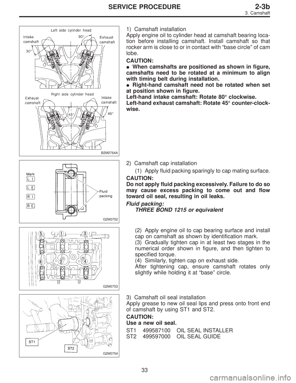
B2M0764A
1) Camshaft installation
Apply engine oil to cylinder head at camshaft bearing loca-
tion before installing camshaft. Install camshaft so that
rocker arm is close to or in contact with“base circle”of cam
lobe.
CAUTION:
�When camshafts are positioned as shown in figure,
camshafts need to be rotated at a minimum to align
with timing belt during installation.
�Right-hand camshaft need not be rotated when set
at position shown in figure.
Left-hand intake camshaft: Rotate 80°clockwise.
Left-hand exhaust camshaft: Rotate 45°counter-clock-
wise.
G2M0752
2) Camshaft cap installation
(1) Apply fluid packing sparingly to cap mating surface.
CAUTION:
Do not apply fluid packing excessively. Failure to do so
may cause excess packing to come out and flow
toward oil seal, resulting in oil leaks.
Fluid packing:
THREE BOND 1215 or equivalent
G2M0753
(2) Apply engine oil to cap bearing surface and install
cap on camshaft as shown by identification mark.
(3) Gradually tighten cap in at least two stages in the
numerical order shown in figure, and then tighten to
specified torque.
(4) Similarly, tighten cap on exhaust side.
After tightening cap, ensure camshaft rotates only
slightly while holding it at“base”circle.
G2M0754
3) Camshaft oil seal installation
Apply grease to new oil seal lips and press onto front end
of camshaft by using ST1 and ST2.
CAUTION:
Use a new oil seal.
ST1 499587100 OIL SEAL INSTALLER
ST2 499597000 OIL SEAL GUIDE
33
2-3bSERVICE PROCEDURE
3. Camshaft
Page 432 of 2890
(7) Further tighten all bolts by 80 to 90°in numerical
sequence.
CAUTION:
Ensure that the total“re-tightening angle”[steps (6)
and (7) above] do not exceed 180°.
3) Install oil level gauge guide attaching bolt (left side
only).
2. INTAKE MANIFOLD
1) Install camshafts, rocker cover and related parts.
G2M0750
Tightening torque: N⋅m (kg-m, ft-lb)
T1: 10±0.7 (1.0±0.07, 7.2±0.5)
T2: 20±2 (2.0±0.2, 14.5±1.4)
44
2-3bSERVICE PROCEDURE
4. Cylinder Head
Page 532 of 2890
B2M0347A
5) Install engine harness onto intake manifold.
6) Connect connectors to throttle position sensor, ignition
coil, fuel injectors, idle air control solenoid valve, purge
control solenoid valve and EGR solenoid valve.
�
1EGR solenoid valve
�
2Throttle position sensor
�
3Idle air control solenoid valve
�
4Purge control solenoid valve
�
5Harness band
B2M0757A
7) Connect engine ground terminal to intake manifold.
B2M0159
D: INSTALLATION
1) Install intake manifold onto cylinder heads.
CAUTION:
Always use new gaskets.
Tightening torque:
25±2 N⋅m (2.5±0.2 kg-m, 18.1±1.4 ft-lb)
G2M0296
2) Connect fuel hoses.
G2M0091
3) Connect connector to oil pressure switch.
14
2-7SERVICE PROCEDURE
4. Intake Manifold
Page 581 of 2890
B2M0313
7) Remove front exhaust pipe and center exhaust pipe
from hanger bracket.
CAUTION:
Be careful not to pull down front exhaust pipe and
center exhaust pipe.
B2M0060
8) Separate front exhaust pipe from front catalytic con-
verter.
B2M0060
B: INSTALLATION
CAUTION:
Replace gaskets with new ones.
1) Install front catalytic converter to front exhaust pipe.
Tightening torque:
30±5 N⋅m (3.1±0.5 kg-m, 22.4±3.6 ft-lb)
B2M0313
2) Install front exhaust pipe and center exhaust pipe.
And temporarily tighten bolt which installs center exhaust
pipe to hanger bracket.
B2M0054
3) Tighten bolts which hold front exhaust pipe onto cylin-
der heads.
Tightening torque:
30±5 N⋅m (3.1±0.5 kg-m, 22.4±3.6 ft-lb)
5
2-9SERVICE PROCEDURE
1. Front Exhaust Pipe and Center Exhaust Pipe
Page 634 of 2890
B2M0347A
5) Install engine harness onto intake manifold.
6) Connect connectors to throttle position sensor, ignition
coil, fuel injectors, idle air control solenoid valve, purge
control solenoid valve and EGR solenoid valve.
�
1EGR solenoid valve
�
2Throttle position sensor
�
3Idle air control solenoid valve
�
4Purge control solenoid valve
�
5Harness band
B2M0757A
7) Connect engine ground terminal to intake manifold.
B2M0159
D: INSTALLATION
1) Install intake manifold onto cylinder heads.
CAUTION:
Always use new gaskets.
Tightening torque:
25±2 N⋅m (2.5±0.2 kg-m, 18.1±1.4 ft-lb)
G2M0296
2) Connect fuel hoses.
G2M0091
3) Connect connector to oil pressure switch.
14
2-7SERVICE PROCEDURE
4. Intake Manifold