Page 188 of 2890
cal
Wiring
Harness
and
Ground
Point
Connector
Connecting
to
Pole
Color
Area
No
.
Name
2
Brown
B-2
Pressure
sources
switching
solenoid
3
Black
B-2
Pressure
sensor
5
Gray
B-2
Mass
air
flow
sensor
2
Gray
B-2
AT
dropping
resistor
4
Gray
B-3
Cruise
control
pump
6B-3Front
wipermotor
2
Black
A-2
FWD
switch
16
Gray
B-3
T4
T
i
12
Gray
B-2
T3
ransmiss
on
6
Gray
B-3
Ignitor
1
Black
B-3
Starter
(Magnet)
2
Gray
B-2
Brake
fluid
level
switch
2
Black
B-3
Vehicle
speed
sensor
3
Dark
gray
B-2
Front
oxygen
sensor
4
B-2
T5
Rear
oxygen
sensor
cord
(Other
models)
4
B-2
Rear
oxygen
sensor
(California
model)
6Light
gray
B-2
E1
12Light
gray
B-2
E2Engine
wiring
harness
16Light
gray
B-2
E3
2
Back
B-3
3
B-3
MIB
1
Brown
B-3
2B-2
Rear
washer
motor
2f
Green
B-3Front
washer
motor
2
.
BULKHEAD
WIRING
HARNESS
AND
GROUND
POINT
(IN
ENGINE
ROOM)
2
I
a
B
C
-r
t
n
GB-4
GB-5
(
rbag
mode
)
B6M0086B
D
1
3
4
4
[D802]
B6M0587A
A
B
C
D
21
Page 189 of 2890

8
.
Electrical
Wiring
Harness
and
Ground
Point
Connector
Connecting
to
No
.
Pole
Color
Area
No
.
Name
131
2
Brown
B-2
Pressure
sources
switching
solenoid
B2
3
Black
B-2
Pressure
sensor
B3
5
Gray
B-2
Mass
air
slow
sensor
B4
2
Gray
B-2
AT
dropping
resistor
B7
4
Gray
B-3
Cruise
control
pump
B8
6B-3Front
wiper
motor
B9
2
Black
A-2
FWD
switch
B11
16
Gray
B-3
T4
T
B12
12
Gray
B-2
T3
ransmission
B13
6
Gray
B-3
Ignitor
B14
1
Black
B-3
Starter
(Magnet)
B16
2
Gray
B-2
Brake
fluid
level
switch
B17
2
Black
B-3
Vehicle
speed
sensor
B18
3
Dark
gray
B-2Front
oxygen
sensor
4B-2
T5Rear
oxygen
sensor
cord(Other
models)
B19
4B-2
Rear
oxygen
sensor
(California
model)
B20
6Light
gray
B-2El
821
12
Light
gray
B-2
E2Engine
wiring
harness
B22
16
Light
gray
B-2
E3
B26
2
Black
B-3
B27
3B-3
MIB
B28
1
Brown
B-3
B29
2B-2
Rear
washer
motor
B110
~
2
f
Green
B-3
~
Front
washer
motor
`
:
Non-colored
2
.
BULKHEAD
WIRING
HARNESS
AND
GROUND
POINT
(IN
ENGINE
ROOM)
1
2
3
a
E
C
DI
Yi-t
~
GB-4GB-5
(Air
`bag
model
(
Airbag
model
~rrE
1
23
4
21
Page 1133 of 2890

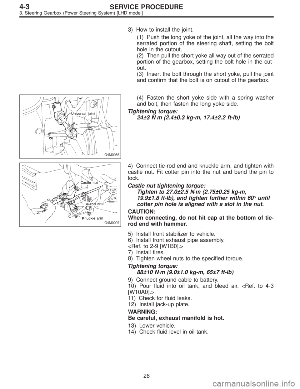
3) How to install the joint.
(1) Push the long yoke of the joint, all the way into the
serrated portion of the steering shaft, setting the bolt
hole in the cutout.
(2) Then pull the short yoke all way out of the serrated
portion of the gearbox, setting the bolt hole in the cut-
out.
(3) Insert the bolt through the short yoke, pull the joint
and confirm that the bolt is on cutout of the gearbox.
G4M0086
(4) Fasten the short yoke side with a spring washer
and bolt, then fasten the long yoke side.
Tightening torque:
24±3 N⋅m (2.4±0.3 kg-m, 17.4±2.2 ft-lb)
G4M0097
4) Connect tie-rod end and knuckle arm, and tighten with
castle nut. Fit cotter pin into the nut and bend the pin to
lock.
Castle nut tightening torque:
Tighten to 27.0±2.5 N⋅m (2.75±0.25 kg-m,
19.9±1.8 ft-lb), and tighten further within 60°until
cotter pin hole is aligned with a slot in the nut.
CAUTION:
When connecting, do not hit cap at the bottom of tie-
rod end with hammer.
5) Install front stabilizer to vehicle.
6) Install front exhaust pipe assembly.
7) Install tires.
8) Tighten wheel nuts to the specified torque.
Tightening torque:
88±10 N⋅m (9.0±1.0 kg-m, 65±7 ft-lb)
9) Connect ground cable to battery.
10) Pour fluid into oil tank, and bleed air.
[W10A0].>
11) Check for fluid leaks.
12) Install jack-up plate.
WARNING:
Be careful, exhaust manifold is hot.
13) Lower vehicle.
14) Check fluid level in oil tank.
26
4-3SERVICE PROCEDURE
3. Steering Gearbox (Power Steering System) [LHD model]
Page 1153 of 2890

G4M0152
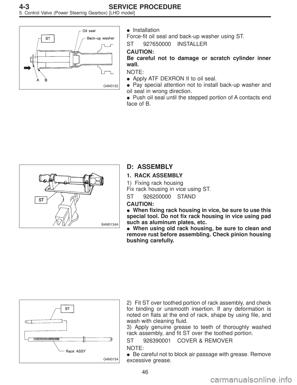
�Installation
Force-fit oil seal and back-up washer using ST.
ST 927650000 INSTALLER
CAUTION:
Be careful not to damage or scratch cylinder inner
wall.
NOTE:
�Apply ATF DEXRON II to oil seal.
�Pay special attention not to install back-up washer and
oil seal in wrong direction.
�Push oil seal until the stepped portion of A contacts end
face of B.
B4M0134A
D: ASSEMBLY
1. RACK ASSEMBLY
1) Fixing rack housing
Fix rack housing in vice using ST.
ST 926200000 STAND
CAUTION:
�When fixing rack housing in vice, be sure to use this
special tool. Do not fix rack housing in vice using pad
such as aluminum plates, etc.
�When using old rack housing, be sure to clean and
remove rust before assembling. Check pinion housing
bushing carefully.
G4M0154
2) Fit ST over toothed portion of rack assembly, and check
for binding or unsmooth insertion. If any deformation is
noted on flats at the end of rack, shape by using file, and
wash with cleaning fluid.
3) Apply genuine grease to teeth of thoroughly washed
rack assembly, and fit ST over the toothed portion.
ST 926390001 COVER & REMOVER
NOTE:
�Be careful not to block air passage with grease. Remove
excessive grease.
46
4-3SERVICE PROCEDURE
5. Control Valve (Power Steering Gearbox) [LHD model]
Page 1641 of 2890
G6M0095
4. #4 SPARK PLUG
1) Disconnect battery ground cable.
B6M0554
2) Remove battery.
B6M0561
3) Remove washer tank mounting bolts.
B6M0562A
4) Disconnect washer tank connectors.
CAUTION:
Do not disconnect washer tank hoses as washer fluid
will leak out from washer tank.
B6M0575A
5) Move washer tank upward.
27
6-1SERVICE PROCEDURE
3. Spark Plug
Page 1646 of 2890
B6M0570A
6) Remove #3 spark plug cord by pulling boot, not cord
itself.
7) For subsequent procedures, refer to the procedure for
#1 spark plug.
G6M0095
4. #4 SPARK PLUG
1) Disconnect battery ground cable.
B6M0554
2) Remove battery.
B6M0561
3) Remove washer tank mounting bolts.
B6M0562A
4) Disconnect washer tank connectors.
CAUTION:
Do not disconnect washer tank hoses as washer fluid
will leak out from washer tank.
32
6-1SERVICE PROCEDURE
3. Spark Plug
Page 2851 of 2890
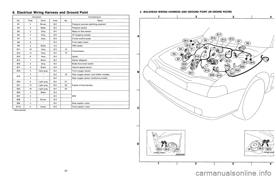
Connector Connecting to
No. Pole Color Area No. Name
B1 2 Brown B-2 Pressure sources switching solenoid
B2 3 Black B-2 Pressure sensor
B3 5 Gray B-2 Mass air flow sensor
B4 2 Gray B-2 AT dropping resistor
B7 4 Gray B-3 Cruise control pump
B8 6 * B-3 Front wiper motor
B9 2 Black A-2 FWD switch
B11 16 Gray B-3 T4
Transmission
B12 12 Gray B-2 T3
B13 6 Gray B-3 Ignitor
B14 1 Black B-3 Starter (Magnet)
B16 2 Gray B-2 Brake fluid level switch
B17 2 Black B-3 Vehicle speed sensor
B18 3 Dark gray B-2 Front oxygen sensor
B194 * B-2 T5 Rear oxygen sensor cord (Other models)
4 * B-2 Rear oxygen sensor (California model)
B20 6 Light gray B-2 E1
Engine wiring harness B21 12 Light gray B-2 E2
B22 16 Light gray B-2 E3
B26 2 Black B-3
M/B B27 3 * B-3
B28 1 Brown B-3
B29 2 * B-2 Rear washer motor
B110 2 Green B-3 Front washer motor
*: Non-colored
121
6-3WIRING DIAGRAM
8. Electrical Wiring Harness and Ground Point