Page 316 of 2890
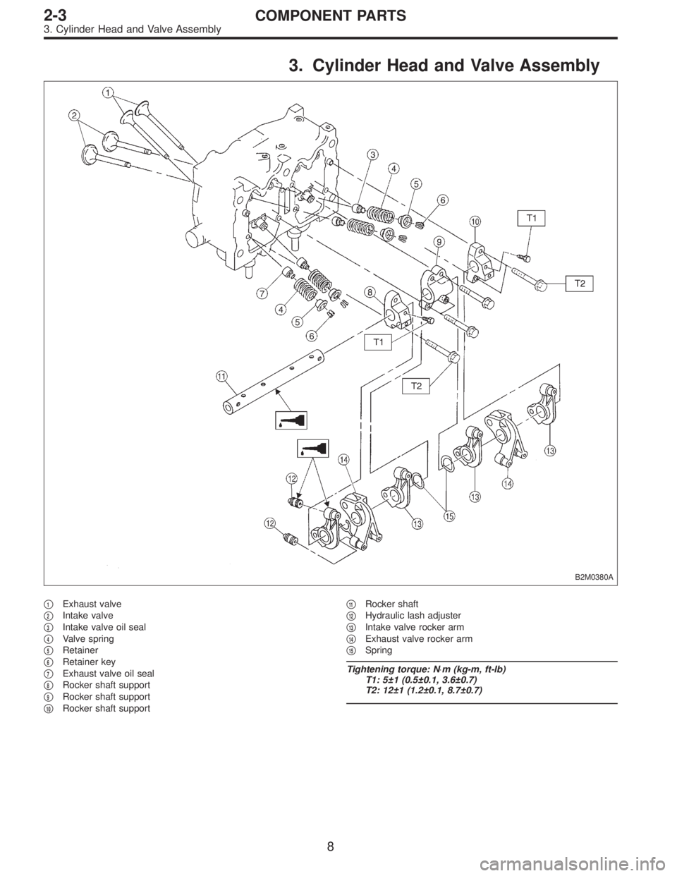
3. Cylinder Head and Valve Assembly
B2M0380A
�1Exhaust valve
�
2Intake valve
�
3Intake valve oil seal
�
4Valve spring
�
5Retainer
�
6Retainer key
�
7Exhaust valve oil seal
�
8Rocker shaft support
�
9Rocker shaft support
�
10Rocker shaft support�
11Rocker shaft
�
12Hydraulic lash adjuster
�
13Intake valve rocker arm
�
14Exhaust valve rocker arm
�
15Spring
Tightening torque: N⋅m (kg-m, ft-lb)
T1: 5±1 (0.5±0.1, 3.6±0.7)
T2: 12±1 (1.2±0.1, 8.7±0.7)
8
2-3COMPONENT PARTS
3. Cylinder Head and Valve Assembly
Page 317 of 2890
4. Cylinder Block
B2M0381A
�1Oil pressure switch
�
2Cylinder block (RH)
�
3Service hole plug
�
4Gasket
�
5Oil separator cover
�
6Water pipe
�
7Oil pump
�
8Front oil seal
�
9Rear oil seal
�
10O-ring
�
11Service hole cover
�
12Cylinder block (LH)
�
13Water pump
�
14Baffle plate
�
15Oil strainer stay
�
16Oil strainer�
17Gasket
�
18Oil pan
�
19Oil drain plug
�
20Gasket
�
21Oil filler pipe
Tightening torque: N⋅m (kg-m, ft-lb)
T1: 5 (0.5, 3.6)
T2: 6.4 (0.65, 4.7)
T3: 10 (1.0, 7)
T4: 25±2 (2.5±0.2, 18.1±1.4)
T5: 47±3 (4.8±0.3, 34.7±2.2)
T6: 69±7 (7.0±0.7, 50.6±5.1)
T7: First 12±2 (1.2±0.2, 8.7±1.4)
Second 12±2 (1.2±0.2, 8.7±1.4)
9
2-3COMPONENT PARTS
4. Cylinder Block
Page 318 of 2890
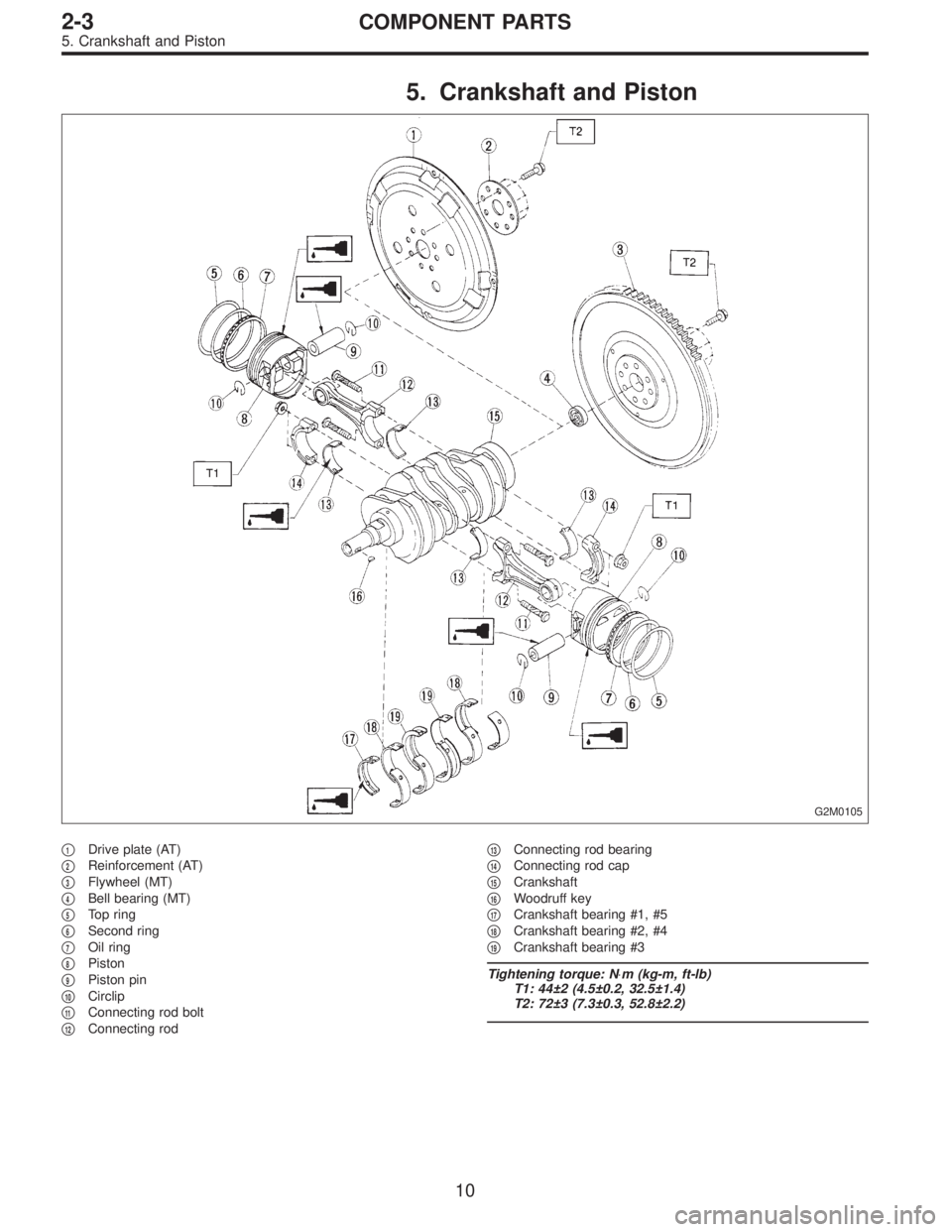
5. Crankshaft and Piston
G2M0105
�1Drive plate (AT)
�
2Reinforcement (AT)
�
3Flywheel (MT)
�
4Bell bearing (MT)
�
5Top ring
�
6Second ring
�
7Oil ring
�
8Piston
�
9Piston pin
�
10Circlip
�
11Connecting rod bolt
�
12Connecting rod�
13Connecting rod bearing
�
14Connecting rod cap
�
15Crankshaft
�
16Woodruff key
�
17Crankshaft bearing #1, #5
�
18Crankshaft bearing #2, #4
�
19Crankshaft bearing #3
Tightening torque: N⋅m (kg-m, ft-lb)
T1: 44±2 (4.5±0.2, 32.5±1.4)
T2: 72±3 (7.3±0.3, 52.8±2.2)
10
2-3COMPONENT PARTS
5. Crankshaft and Piston
Page 323 of 2890
 Fill rocker arm’s oil reservoir with engine oil and install
lash adjuster.
CAUTION:
�Do not rotate lash adjuster during installation.
�Be careful not to scratch the oil seal.
B2M0414
CAUTION:
Whe")
6) Fill rocker arm’s oil reservoir with engine oil and install
lash adjuster.
CAUTION:
�Do not rotate lash adjuster during installation.
�Be careful not to scratch the oil seal.
B2M0414
CAUTION:
When removing valve rocker assembly, keep the
assembly soaked in engine oil, or position it with air
bleeding orifice on rocker arm facing upward as
shown. This prevents oil leakage from and air entering
into the hydraulic lash adjuster. Failure to do so may
cause air to enter the hydraulic lash adjuster, causing
loss in performance.
B2M0382B
7) Temporarily and equally tighten bolts�1through�4.Do
not allow knock pin to catch valve rocker assembly.
8) Tighten bolts�
5through�8to specified torque.
9) Tighten bolts�
1through�4to specified torque.
Tightening torque:
12±1 N⋅m (1.2±0.1 kg-m, 8.7±0.7 ft-lb)
10) Install rocker covers.
Tightening torque:
5±1 N⋅m (0.5±0.1 kg-m, 3.6±0.7 ft-lb)
11) Connect harness connectors, hoses, etc. to their posi-
tions.
14
2-3SERVICE PROCEDURE
2. Hydraulic Lash Adjuster
Page 331 of 2890
C: INSTALLATION
1. SPROCKET
B2M0416B
Tightening torque: N⋅m (kg-m, ft-lb)
T1: 5±1 (0.5±0.1, 3.6±0.7)
T2: 25±2 (2.5±0.2, 18.1±1.4)
T3: 78±5 (8.0±0.5, 57.9±3.6)
G2M0114
1) Install right side belt cover No. 2.
2) Install tensioner bracket.
3) Install left side belt cover No. 2.
4) Install crankshaft sprocket.
5) Install right side camshaft sprocket and left side cam-
shaft sprocket. To lock camshaft use ST.
ST 499207100 CAMSHAFT SPROCKET WRENCH
CAUTION:
Do not confuse left and right side camshaft sprockets
during installation. The left side camshaft sprocket is
identified by a projection used to monitor cam angle
sensor.
22
2-3SERVICE PROCEDURE
3. Timing Belt
Page 332 of 2890
2. BELT TENSIONER AND IDLER
B2M0070A
Tightening torque: N⋅m (kg-m, ft-lb)
T: 39±4 (4.0±0.4, 28.9±2.9)
B2M0109A
1) Installation of belt tension adjuster
Insert stopper pin 1.5 mm (0.059 in) diameter into place
while pushing tension adjuster rod into body using a press.
CAUTION:
�Do not allow press pressure to exceed 9,807 N (1,000
kg, 2,205 lb).
�Do not release press pressure until stopper pin is
completely inserted.
�Push tension adjuster rod vertically.
�Press-in the push rod gradually taking three minutes
or more.
23
2-3SERVICE PROCEDURE
3. Timing Belt
Page 333 of 2890
2) Install belt tensioner and spacer.
3) Install belt idler.
B2M0110
4) Temporarily tighten bolts while belt tension adjuster is
pushed all the way to the right.
3. TIMING BELT
B2M0071A
Tightening torque: N⋅m (kg-m, ft-lb)
T1: 25±2 (2.5±0.2, 18.1±1.4)
T2: 39±4 (4.0±0.4, 28.9±2.9)
24
2-3SERVICE PROCEDURE
3. Timing Belt
Page 335 of 2890
4. CRANKSHAFT PULLEY AND BELT COVER
G2M0126
Tightening torque: N⋅m (kg-m, ft-lb)
T1: 5±1 (0.5±0.1, 3.6±0.7)
T2: 108
+10
�5(11+1.0
�0.5, 79.6+7.2
�3.6)
1) Install front belt cover.
2) Install right side belt cover.
3) Install left side belt cover.
4) Install crankshaft pulley.
G2M0108
5) Install pulley bolt.
To lock crankshaft, use ST.
ST 499977000 CRANKSHAFT PULLEY WRENCH
6) Install V-belt.
26
2-3SERVICE PROCEDURE
3. Timing Belt


T1: 5±1 (0.5±0.1, 3.6±0.7)
T2: 25±2 (2.5±0.2, 18.1±1.4)
T3: 78±5 (8.0±0.5, 57.9±3.6)
G2M0114
1) Install right side")

T: 39±4 (4.0±0.4, 28.9±2.9)
B2M0109A
1) Installation of belt tension adjuster
Insert stopper pin 1.5 mm (0.059 in) diamet")
 Install belt tensioner and spacer.
3) Install belt idler.
B2M0110
4) Temporarily tighten bolts while belt tension adjuster is
pushed all the way to the right.
3. TIMING BELT
B2M0071A
Tightening tor")

T1: 5±1 (0.5±0.1, 3.6±0.7)
T2: 108
+10
�5(11+1.0
�0.5, 79.6+7.2
�3.6)
1) Install front belt cover.
2) Install righ")