Page 396 of 2890
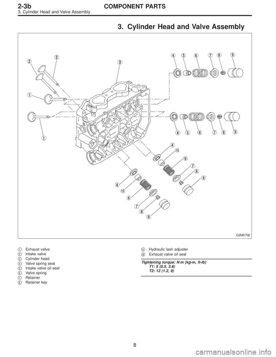
3. Cylinder Head and Valve Assembly
G2M0706
�1Exhaust valve
�
2Intake valve
�
3Cylinder head
�
4Valve spring seat
�
5Intake valve oil seal
�
6Valve spring
�
7Retainer
�
8Retainer key�
9Hydraulic lash adjuster
�
10Exhaust valve oil seal
Tightening torque: N⋅m (kg-m, ft-lb)
T1: 5 (0.5, 3.6)
T2: 12 (1.2, 9)
8
2-3bCOMPONENT PARTS
3. Cylinder Head and Valve Assembly
Page 397 of 2890
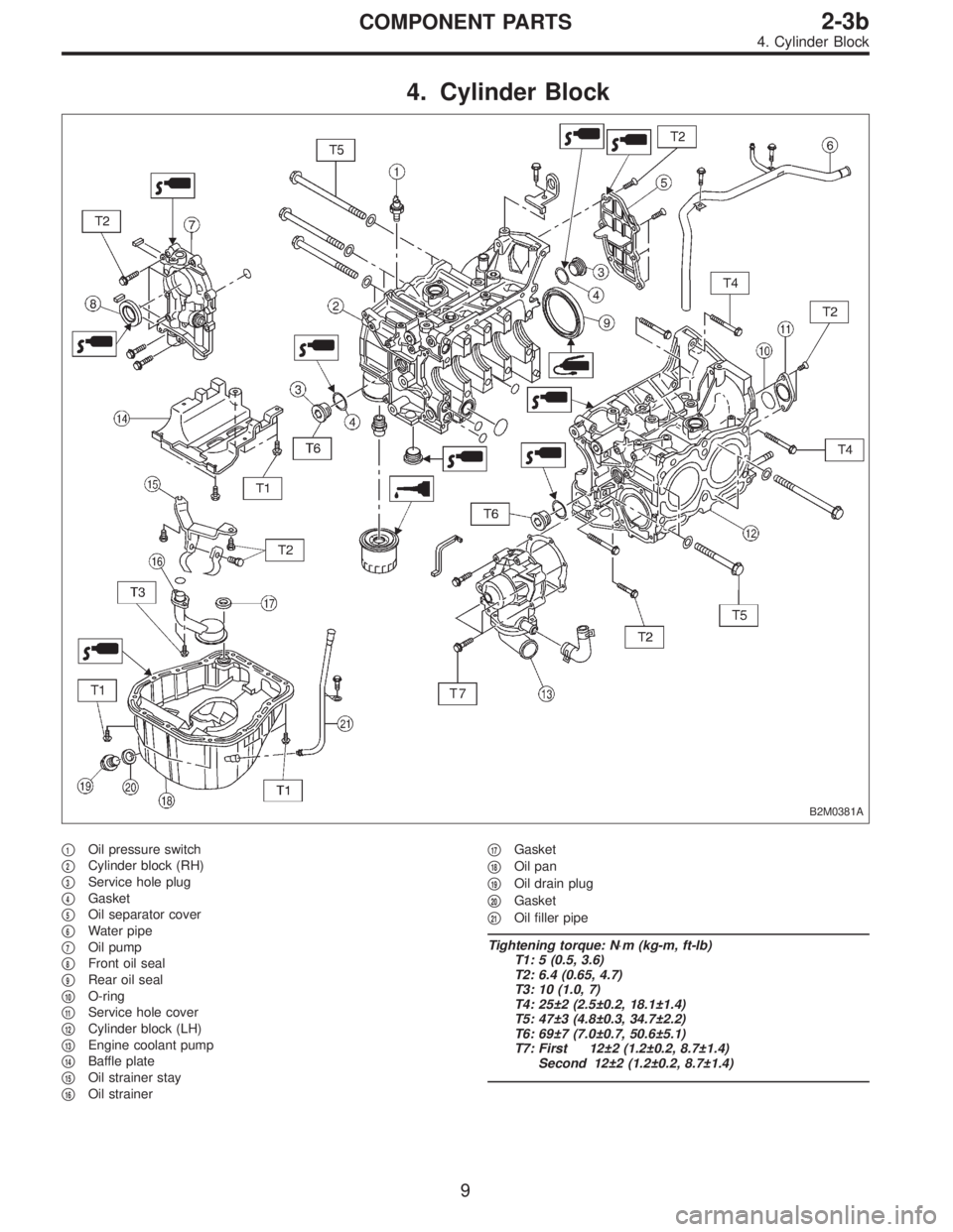
4. Cylinder Block
B2M0381A
�1Oil pressure switch
�
2Cylinder block (RH)
�
3Service hole plug
�
4Gasket
�
5Oil separator cover
�
6Water pipe
�
7Oil pump
�
8Front oil seal
�
9Rear oil seal
�
10O-ring
�
11Service hole cover
�
12Cylinder block (LH)
�
13Engine coolant pump
�
14Baffle plate
�
15Oil strainer stay
�
16Oil strainer�
17Gasket
�
18Oil pan
�
19Oil drain plug
�
20Gasket
�
21Oil filler pipe
Tightening torque: N⋅m (kg-m, ft-lb)
T1: 5 (0.5, 3.6)
T2: 6.4 (0.65, 4.7)
T3: 10 (1.0, 7)
T4: 25±2 (2.5±0.2, 18.1±1.4)
T5: 47±3 (4.8±0.3, 34.7±2.2)
T6: 69±7 (7.0±0.7, 50.6±5.1)
T7: First 12±2 (1.2±0.2, 8.7±1.4)
Second 12±2 (1.2±0.2, 8.7±1.4)
9
2-3bCOMPONENT PARTS
4. Cylinder Block
Page 398 of 2890
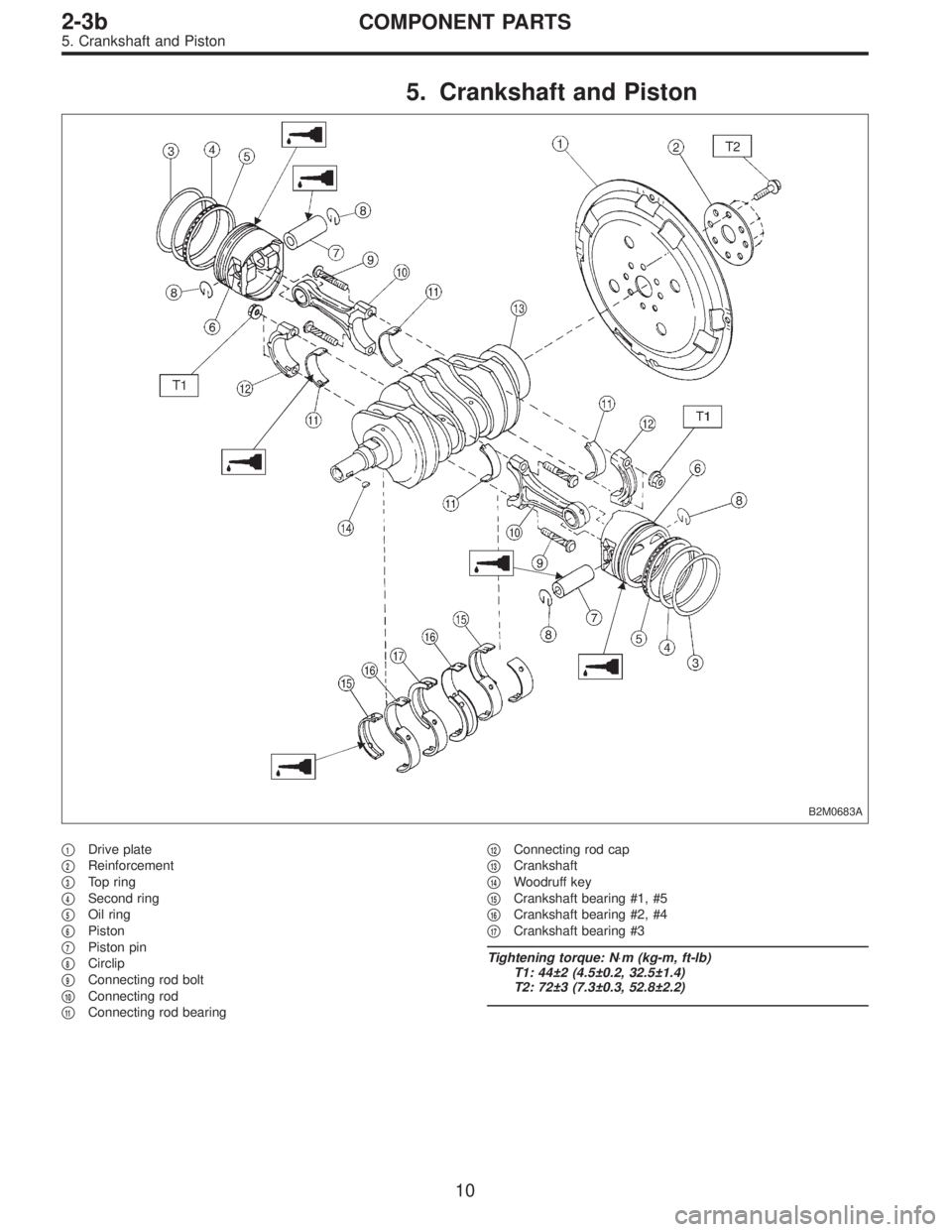
5. Crankshaft and Piston
B2M0683A
�1Drive plate
�
2Reinforcement
�
3Top ring
�
4Second ring
�
5Oil ring
�
6Piston
�
7Piston pin
�
8Circlip
�
9Connecting rod bolt
�
10Connecting rod
�
11Connecting rod bearing�
12Connecting rod cap
�
13Crankshaft
�
14Woodruff key
�
15Crankshaft bearing #1, #5
�
16Crankshaft bearing #2, #4
�
17Crankshaft bearing #3
Tightening torque: N⋅m (kg-m, ft-lb)
T1: 44±2 (4.5±0.2, 32.5±1.4)
T2: 72±3 (7.3±0.3, 52.8±2.2)
10
2-3bCOMPONENT PARTS
5. Crankshaft and Piston
Page 408 of 2890
5. SPROCKET
1) Check sprocket teeth for abnormal wear and scratches.
2) Make sure there is no free play between sprocket and
key.
3) Check crankshaft sprocket notch for sensor for damage
and contamination of foreign matter.
C: INSTALLATION
1. SPROCKET
B2M0691B
Tightening torque: N⋅m (kg-m, ft-lb)
T1: 4.9±0.5 (0.5±0.05, 3.6±0.4)
T2: 25±2 (2.5±0.2, 18±1.4)
T3: 78±5 (8.0±0.5, 58±3.6)
B2M0738
1) Install right-hand belt cover No. 2.
20
2-3bSERVICE PROCEDURE
2. Timing Belt
Page 410 of 2890
2. BELT TENSIONER AND IDLER
B2M0690B
Tightening torque: N⋅m (kg-m, ft-lb)
T1: 25±2 (2.5±0.2, 18±1.4)
T2: 39±4 (4.0±0.4, 29±2.9)
G2M0119
1) Installation of belt tensioner adjuster
(1) Insert stopper pin 1.5 mm (0.059 in) dia. into place
while pushing tension adjuster rod into body using a
press.
CAUTION:
�Do not allow press pressure to exceed 9,807 N (1,000
kg, 2,205 lb).
�Do not release press pressure until stopper pin is
completely inserted.
�Push tension adjuster rod vertically.
�Press-in the push rod gradually, taking three min-
utes or more.
22
2-3bSERVICE PROCEDURE
2. Timing Belt
Page 411 of 2890
G2M0725
(2) Temporarily tighten bolts while tension adjuster is
pushed all the way to the right.
G2M0726
2) Install belt tensioner.
3) Install belt idler.
4) Install belt idler No. 2.
3. TIMING BELT
B2M0693A
Tightening torque: N⋅m (kg-m, ft-lb)
T: 39±4 (4.0±0.4, 29±2.9)
23
2-3bSERVICE PROCEDURE
2. Timing Belt
Page 416 of 2890
4. CRANKSHAFT PULLEY AND BELT COVER
B2M0684B
Tightening torque: N⋅m (kg-m, ft-lb)
T1: 5±0.5 (0.5±0.05, 3.6±0.4)
T2: 127±5 (13.0±0.5, 94.0±3.6)
B2M0731
1) Install front belt cover.
B2M0730
2) Install right-hand belt cover.
28
2-3bSERVICE PROCEDURE
2. Timing Belt
Page 420 of 2890
G2M0138
5) Check cam face condition; remove minor faults by
grinding with oil stone. Measure the cam height H; replace
if the limit has been exceeded.
Standard:
Intake 41.68—41.78 mm (1.6409—1.6449 in)
Exhaust 41.98—42.08 mm (1.6528—1.6567 in)
Limit:
Intake 41.52 mm (1.6346 in)
Exhaust 41.82 mm (1.6465 in)
G2M0748
6) Measure the thrust clearance of camshaft with dial
gauge. If the clearance exceeds the limit, replace caps and
cylinder head as a set. If necessary replace camshaft.
Standard:
0.040—0.080 mm (0.0016—0.0031 in)
Limit:
0.1 mm (0.004 in)
C: INSTALLATION
1. CAMSHAFT
G2M0750
Tightening torque: N⋅m (kg-m, ft-lb)
T1: 10±0.7 (1.0±0.07, 7.2±0.5)
T2: 20±2 (2.0±0.2, 14.5±1.4)
32
2-3bSERVICE PROCEDURE
3. Camshaft
 Check sprocket teeth for abnormal wear and scratches.
2) Make sure there is no free play between sprocket and
key.
3) Check crankshaft sprocket notch for sensor for damage
and contamina")

T1: 25±2 (2.5±0.2, 18±1.4)
T2: 39±4 (4.0±0.4, 29±2.9)
G2M0119
1) Installation of belt tensioner adjuster
(1) Insert st")
 Temporarily tighten bolts while tension adjuster is
pushed all the way to the right.
G2M0726
2) Install belt tensioner.
3) Install belt idler.
4) Install belt idler No. 2.
3. TIMING BELT
B")

T1: 5±0.5 (0.5±0.05, 3.6±0.4)
T2: 127±5 (13.0±0.5, 94.0±3.6)
B2M0731
1) Install front belt cover.
B2M0730
2) I")
 Check cam face condition; remove minor faults by
grinding with oil stone. Measure the cam height H; replace
if the limit has been exceeded.
Standard:
Intake 41.68—41.78 mm (1.6409—1.644")