Page 375 of 2890
D: ASSEMBLY
1. CRANKSHAFT AND PISTON
B2M0127A
Tightening torque: N⋅m (kg-m, ft-lb)
T: 44±2 (4.5±0.2, 32.5±1.4)
1) Install connecting rod bearings on connecting rods and
connecting rod caps.
CAUTION:
Apply oil to the surfaces of the connecting rod bear-
ings.
2) Install connecting rod on crankshaft.
CAUTION:
Position each connecting rod with the side marked
facing forward.
3) Install connecting rod cap with connecting rod nut.
Ensure the arrow on connecting rod cap faces the front
during installation.
CAUTION:
�Each connecting rod has its own mating cap. Make
sure that they are assembled correctly by checking
their matching number.
�When tightening the connecting rod nuts, apply oil
on the threads.
65
2-3SERVICE PROCEDURE
7. Cylinder Block
Page 377 of 2890
B2M0087A
2. CYLINDER BLOCK
1) Install ST to cylinder block, then install crankshaft bear-
ings.
ST 499817000 ENGINE STAND
CAUTION:
Remove oil the mating surface of bearing and cylinder
block before installation. Also apply a coat of engine
oil to crankshaft pins.
2) Position crankshaft on the #2 and #4 cylinder block.
Tightening torque:
T1: 25±2 N⋅m (2.5±0.2 kg-m, 18.1±1.4 ft-lb)
T2: 47±3 N⋅m (4.8±0.3 kg-m, 34.7±2.2 ft-lb)
67
2-3SERVICE PROCEDURE
7. Cylinder Block
Page 378 of 2890
G2M0185
3) Apply fluid packing to the mating surface of #1 and #3
cylinder block, and position it on #2 and #4 cylinder block.
Fluid packing:
THREE BOND 1215 or equivalent
CAUTION:
Do not allow fluid packing to jut into O-ring grooves,
oil passages, bearing grooves, etc.
B2M0088A
4) Temporarily tighten 10 mm cylinder block connecting
bolts in numerical order shown in Figure.
5) Tighten 10 mm cylinder block connecting bolts in
numerical order.
Tightening torque:
47±3 N⋅m (4.8±0.3 kg-m, 34.7±2.2 ft-lb)
B2M0089A
6) Tighten 8 mm and 6 mm cylinder block connecting bolts
in numerical order shown in Figure.
Tightening torque:
�
1—�7: 25±2 N⋅m
(2.5±0.2 kg-m, 18.1±1.4 ft-lb)
�
8: 6.4 N⋅m (0.65 kg-m, 4.7 ft-lb)
G2M0186
7) Install rear oil seal by using ST1 and ST2.
ST1 499597100 OIL SEAL GUIDE
ST2 499587200 OIL SEAL INSTALLER
68
2-3SERVICE PROCEDURE
7. Cylinder Block
Page 379 of 2890
3. PISTON AND PISTON PIN (#1 AND #2)
B2M0128A
Tightening torque: N⋅m (kg-m, ft-lb)
T: 69±7 (7.0±0.7, 50.6±5.1)
G2M0188
1) Installing piston
(1) Turn cylinder block so that #1 and #2 cylinders face
upward.
(2) Using ST1, turn crankshaft so that #1 and #2 con-
necting rods are set at bottom dead center.
ST1 499987500 CRANKSHAFT SOCKET
(3) Apply a coat of engine oil to pistons and cylinders
and insert pistons in their cylinders by using ST2.
ST2 498747100 PISTON GUIDE
G2M0189
2) Installing piston pin
(1) Insert ST3 into service hole to align piston pin hole
with connecting rod small end.
CAUTION:
Apply a coat of engine oil to ST3 before insertion.
ST3 499017100 PISTON PIN GUIDE
69
2-3SERVICE PROCEDURE
7. Cylinder Block
Page 381 of 2890
4. PISTON AND PISTON PIN (#3 AND #4)
B2M0129A
Tightening torque: N⋅m (kg-m, ft-lb)
T1: 6.4 (0.65, 4.7)
T2: 69±7 (7.0±0.7, 50.6±5.1)
Turn cylinder block so that #3 and #4 cylinders face
upward. Using the same procedures as used for #1 and #2
cylinders, install pistons and piston pins.
71
2-3SERVICE PROCEDURE
7. Cylinder Block
Page 382 of 2890
E: INSTALLATION
1. OIL PUMP AND ENGINE COOLANT PUMP
B2M0124B
Tightening torque: N⋅m (kg-m, ft-lb)
T1: 5 (0.5, 3.6)
T2: 6.4 (0.65, 4.7)
T3: 10 (1.0, 7)
T4: 72±3 (7.3±0.3, 52.8±2.2)
T5: First 12±2 (1.2±0.2, 8.7±1.4)
Second 12±2 (1.2±0.2, 8.7±1.4)
72
2-3SERVICE PROCEDURE
7. Cylinder Block
Page 394 of 2890
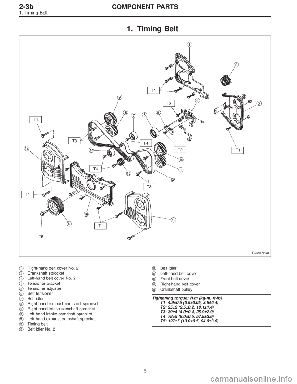
1. Timing Belt
B2M0726A
�1Right-hand belt cover No. 2
�
2Crankshaft sprocket
�
3Left-hand belt cover No. 2
�
4Tensioner bracket
�
5Tensioner adjuster
�
6Belt tensioner
�
7Belt idler
�
8Right-hand exhaust camshaft sprocket
�
9Right-hand intake camshaft sprocket
�
10Left-hand intake camshaft sprocket
�
11Left-hand exhaust camshaft sprocket
�
12Timing belt
�
13Belt idler No. 2�
14Belt idler
�
15Left-hand belt cover
�
16Front belt cover
�
17Right-hand belt cover
�
18Crankshaft pulley
Tightening torque: N⋅m (kg-m, ft-lb)
T1: 4.9±0.5 (0.5±0.05, 3.6±0.4)
T2: 25±2 (2.5±0.2, 18.1±1.4)
T3: 39±4 (4.0±0.4, 28.9±2.9)
T4: 78±5 (8.0±0.5, 57.9±3.6)
T5: 127±5 (13.0±0.5, 94.0±3.6)
6
2-3bCOMPONENT PARTS
1. Timing Belt
Page 395 of 2890

�
2Rocker cover gasket (RH)
�
3Oil separator cover
�
4Gasket
�
5Intake camshaft cap (Front RH)
�
6Intake camshaft cap (Center RH)
�
7Intake c")
2. Cylinder Head and Camshaft
B2M0681A
�1Rocker cover (RH)
�
2Rocker cover gasket (RH)
�
3Oil separator cover
�
4Gasket
�
5Intake camshaft cap (Front RH)
�
6Intake camshaft cap (Center RH)
�
7Intake camshaft cap (Rear RH)
�
8Intake camshaft (RH)
�
9Exhaust camshaft cap (Front RH)
�
10Exhaust camshaft cap (Center RH)
�
11Exhaust camshaft cap (Rear RH)
�
12Exhaust camshaft (RH)
�
13Intake valve guide�
14Exhaust valve guide
�
15Cylinder head bolt
�
16Oil seal
�
17Cylinder head (RH)
�
18Cylinder head gasket (RH)
�
19Cylinder head gasket (LH)
�
20Cylinder head (LH)
�
21Intake camshaft (LH)
�
22Exhaust camshaft (LH)
�
23Intake camshaft cap (Front LH)
�
24Intake camshaft cap (Center LH)
�
25Intake camshaft cap (Rear LH)
�
26Exhaust camshaft (Front LH)�
27Exhaust camshaft cap (Center LH)
�
28Exhaust camshaft cap (Rear LH)
�
29Rocker cover gasket (LH)
�
30Rocker cover (LH)
�
31Oil filler cap
�
32Gasket
�
33Oil filler duct
�
34Gasket
Tightening torque: N⋅m (kg-m, ft-lb)
T1: Refer to 2-3b [W4E1].
T2: 5 (0.5, 3.6)
T3: 10 (1.0, 7)
7
2-3bCOMPONENT PARTS
2. Cylinder Head and Camshaft

T: 44±2 (4.5±0.2, 32.5±1.4)
1) Install connecting rod bearings on connecting rods and
connecting rod caps.
CAUTI")
 Install ST to cylinder block, then install crankshaft bear-
ings.
ST 499817000 ENGINE STAND
CAUTION:
Remove oil the mating surface of bearing and cylinder
block before in")
 Apply fluid packing to the mating surface of #1 and #3
cylinder block, and position it on #2 and #4 cylinder block.
Fluid packing:
THREE BOND 1215 or equivalent
CAUTION:
Do not allow fluid")

B2M0128A
Tightening torque: N⋅m (kg-m, ft-lb)
T: 69±7 (7.0±0.7, 50.6±5.1)
G2M0188
1) Installing piston
(1) Turn cylinder block so that #1 and #2 cylinders fac")

B2M0129A
Tightening torque: N⋅m (kg-m, ft-lb)
T1: 6.4 (0.65, 4.7)
T2: 69±7 (7.0±0.7, 50.6±5.1)
Turn cylinder block so that #3 and #4 cylinders face
upward. Us")

T1: 5 (0.5, 3.6)
T2: 6.4 (0.65, 4.7)
T3: 10 (1.0, 7)
T4: 72±3 (7.3±0.3, 52.8±2.2)
T5: First 12±2")