Page 340 of 2890
D: ASSEMBLY
B2M0383B
Tightening torque: N⋅m (kg-m, ft-lb)
T: 5±1 (0.5±0.1, 3.6±0.7)
1) After bleeding air from hydraulic lash adjuster, position
hydraulic lash adjuster in valve rocker arm while dipping in
engine oil.
CAUTION:
�Fill rocker arm oil reservoir chamber with engine oil.
�Install a new hydraulic lash adjuster O-ring, being
careful not to scratch it.
�Do not attempt to rotate hydraulic lash adjuster dur-
ing installation.
2) Arrange valve rocker arms, springs and shaft supports
in assembly order and insert valve rocker shaft. Ensure
that cutout portion of rocker shaft faces oil holes�
Ain shaft
supports.
CAUTION:
Valve rocker arms, rocker shaft and shaft supports
have identification marks. Ensure parts with same
markings are properly assembled.
3) Install valve rocker shaft securing bolts while aligning
shaft“lock”holes�
Bwith bolts.
31
2-3SERVICE PROCEDURE
4. Valve Rocker Assembly
Page 341 of 2890
E: INSTALLATION
B2M0418B
Tightening torque: N⋅m (kg-m, ft-lb)
T1: 5±1 (0.5±0.1, 3.6±0.7)
T2: 12±1 (1.2±0.1, 8.7±0.7)
B2M0382B
1) Installation of valve rocker assembly
(1) Temporarily tighten bolts�
1through�4equally as
shown in Figure.
CAUTION:
Do not allow valve rocker assembly to gouge knock
pins.
(2) Tighten bolts�
5through�8to specified torque.
(3) Tighten bolts�
1through�4to specified torque.
2) Install rocker cover and connect PCV hose.
32
2-3SERVICE PROCEDURE
4. Valve Rocker Assembly
Page 345 of 2890
C: INSTALLATION
1. CAMSHAFT LH
B2M0384B
Tightening torque: N⋅m (kg-m, ft-lb)
T1: 10 (1.0, 7)
T2: 16 (1.6, 12)
1) Apply a coat of engine oil to camshaft journals and
install camshaft LH.
2) Apply a coat of engine oil or grease to O-ring.
3) Install O-ring to camshaft support.
CAUTION:
Use a new O-ring.
4) Install camshaft support.
G2M0141
5) Apply a coat of grease to oil seal lips and install oil seal
on camshaft support by using ST1 and ST2.
CAUTION:
Use a new oil seal.
ST1 499597000 OIL SEAL GUIDE
ST2 499587100 OIL SEAL INSTALLER
6) Install oil level gauge guide bolt.
36
2-3SERVICE PROCEDURE
5. Camshaft
Page 346 of 2890
2. CAMSHAFT RH
B2M0385B
Tightening torque: N⋅m (kg-m, ft-lb)
T: 16 (1.6, 12)
1) Apply a coat of engine oil to camshaft journals and
install camshaft RH.
2) Apply a coat of engine oil or grease to O-ring.
3) Install O-ring to camshaft support.
CAUTION:
Use a new O-ring.
4) Install camshaft support.
G2M0143
5) Install oil seal by using ST1 and ST2.
CAUTION:
Use a new oil seal.
ST1 499597000 OIL SEAL GUIDE
ST2 499587100 OIL SEAL INSTALLER
37
2-3SERVICE PROCEDURE
5. Camshaft
Page 347 of 2890
3. RELATED PARTS
1) Install valve rocker assembly.
B2M0418B
Tightening torque: N⋅m (kg-m, ft-lb)
T1: 5±1 (0.5±0.1, 3.6±0.7)
T2: 12±1 (1.2±0.1, 8.7±0.7)
2) Install timing belt, camshaft sprockets and related parts.
6. Cylinder Head
A: REMOVAL
1. INTAKE MANIFOLD
1) Release fuel pressure.
2) Drain engine coolant.
3) Remove intake manifold.
4) Remove engine coolant pipe.
38
2-3SERVICE PROCEDURE
5. Camshaft - 6. Cylinder Head
Page 348 of 2890
3. RELATED PARTS
1) Install valve rocker assembly.
B2M0418B
Tightening torque: N⋅m (kg-m, ft-lb)
T1: 5±1 (0.5±0.1, 3.6±0.7)
T2: 12±1 (1.2±0.1, 8.7±0.7)
2) Install timing belt, camshaft sprockets and related parts.
6. Cylinder Head
A: REMOVAL
1. INTAKE MANIFOLD
1) Release fuel pressure.
2) Drain engine coolant.
3) Remove intake manifold.
4) Remove engine coolant pipe.
38
2-3SERVICE PROCEDURE
5. Camshaft - 6. Cylinder Head
Page 351 of 2890

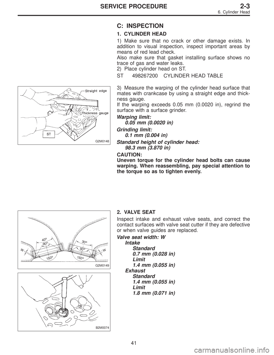
C: INSPECTION
1. CYLINDER HEAD
1) Make sure that no crack or other damage exists. In
addition to visual inspection, inspect important areas by
means of red lead check.
Also make sure that gasket installing surface shows no
trace of gas and water leaks.
2) Place cylinder head on ST.
ST 498267200 CYLINDER HEAD TABLE
G2M0148
3) Measure the warping of the cylinder head surface that
mates with crankcase by using a straight edge and thick-
ness gauge.
If the warping exceeds 0.05 mm (0.0020 in), regrind the
surface with a surface grinder.
Warping limit:
0.05 mm (0.0020 in)
Grinding limit:
0.1 mm (0.004 in)
Standard height of cylinder head:
98.3 mm (3.870 in)
CAUTION:
Uneven torque for the cylinder head bolts can cause
warping. When reassembling, pay special attention to
the torque so as to tighten evenly.
G2M0149
B2M0074
2. VALVE SEAT
Inspect intake and exhaust valve seats, and correct the
contact surfaces with valve seat cutter if they are defective
or when valve guides are replaced.
Valve seat width: W
Intake
Standard
0.7 mm (0.028 in)
Limit
1.4 mm (0.055 in)
Exhaust
Standard
1.4 mm (0.055 in)
Limit
1.8 mm (0.071 in)
41
2-3SERVICE PROCEDURE
6. Cylinder Head
Page 356 of 2890
D: ASSEMBLY
B2M0121B
Tightening torque: N⋅m (kg-m, ft-lb)
T1: 5±1 (0.5±0.1, 3.6±0.7)
T2: 10 (1.0, 7)
T3: 12±1 (1.2±0.1, 8.7±0.7)
T4: 16 (1.6, 12)
1) Install plug (cylinder head LH) by using ST.
ST 499587100 OIL SEAL INSTALLER
2) Installation of valve spring and valve
(1) Place cylinder head on ST.
ST 498267200 CYLINDER HEAD TABLE
(2) Coat stem of each valve with engine oil and insert
valve into valve guide.
CAUTION:
When inserting valve into valve guide, use special care
not to damage the oil seal lip.
46
2-3SERVICE PROCEDURE
6. Cylinder Head